Digital Communications System Programming Instructions This publication reflects software releases through 2.A. COMDWm Printed in U.S.A. IMI66-123.
CERTIFBEC IS0 sooa Corndial’s Quality Management System 1s Certified To The IS0 9001 Standard.
Table Of Contents 1 Understanding General Programming Information 1.0 1.1 1.2 1.3 1.4 1.5 1.6 1.7 1.
DXP Plus Programming Instructions /M/66-123 6 Programming Sysfem Features 6.1 6.2 6.3 6.4 6.5 6.6 6.7 6.8 6.9 6.10 6.11 6.12 6.13 7 Programming Sfafion Features 7.1 7.2 7.3 7.4 7.5 8 Programming Station Class Of Service Features Programming Station Features Square/Non-Square System (Button Mapping By Station) Telephone Types (Phone Types) Copy Model COS, Station, Button Map (Block Programming) Programming Line Features 8.1 8.2 8.3 8.4 8.5 8.6 8.7 8.
DXP Plus Programming Instructions 10 /M/66-123 Programming Call Costing and Station MessageRetail Accounting and Reports (SMDABMDR Programmingj 10.1 SMDAKMDR Parameters 10.2 SMDA Reports 10.3 Account Codes (Forced, With Positive Verification) 10.4 Emergency Numbers 10.5 Authorization Code 11 Programming Toll Restriction 11.1 11.2 11.3 11.4 11.5 11.6 11.7 72 Enabling Automatic Route Selection 12.1 12.2 12.3 12.4 12.5 12.
DXP Plus Programming Instructions /M/66-123 14 Programming For Peripheral Devices 14.1 14.2 14.3 14.4 14.5 14.6 15 Caller ID Programming Tracker Paging System Programming Digital Voice Announce Programming PC Attendant Position Programming Voice Mail Programming Modem Setup Configuring The System’s Board Layout 15.1 15.2 15.3 15.4 15.
Understanding General Programming Information I.0 Determining Your Equipment Needs Program the DXP Plus digital communications system from a personal computer (PC) that meets the following requirements: l Intel* 80386SX-33 processor (minimum requirement), l four megabytes of random access memory (minimum requirement), l 3.
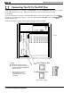
DXP Plus Programming Instructions IM166-123 1.1 Connecting The PC To The DXP Plus Connect the serial data port of the PC to the maintenance port of the DXP Plus central processor (CPU) board. The maintenance port is a dedicated serial data port reserved exclusively for system programming. You can connect the PC remotely to the DXP Plus using a modem and a telephone line. The DXP Phs includes its own modem that someone on site can connect between the CPU board’s modem port and an outside telephone line.
IlW66-123 DXP Plus Programming Instructions 1.2 Installing The VMMI Software Program The VMMI software is your entry to the DXP Plus system. Before you can login to the system, you must first load the VMMI software into your PC’s memory. When installing the VMMI software, your PC need not be connected to the DXP Plus. 1. Turn on your PC and load your Windows software. 2. Insert the VMMI software disk in your computer’s floppy disk drive. 3.
DXP Plus Programming Instructions /M/66-123 1.3 Performing The Login Procedure Once you have loaded the VMMI software using the Section 1.2 discussion, you can login to the system by performing the following procedure. 1. Turn on your PC and load the Windows software. 2. Select the VMMI program from the Windows Program Manager screen 3. From the VMMI window, select the DXP pull-down menu. 4. From the DXP pull-down menu, select Login. 5. From the Login window, select the login mode: 6.
1.4 ReLoading Or Up-Grading The System Software The DXP Plus includes system software when it ships from the factory. At initial system installation, you do not need to load the system software to make the system operational. Should you need to later reload the system software (for software up-grade purposes for example), you can do so using the supplied system software disk. Use Windows File Manager or MS-DOS commands to save the disk’s information from your computer’s floppy drive to its hard drive.
DXP Plus Programming Instructions ItW66- 123 1.5 Using VMMI Software To Translate A DXP Database You can use the VMMI software to translate the database residing in a DXP to a format that is compatible with the DXP Plus, and load that database into the DXP Plus system. While translating data, your PC need not be connected to the DXP Plus. Before you translate a DXP database, determine the revision level of the DXP system software. If the DXP system software revision is 8.
Saving the DXP Dafabase NOTE: This programming procedure details steps that one follows when using the communications software program known as PROCOMM (produced by Datastorm Technologies). If you are using a different communications software, your steps may be different. 1. Connect your PC to the DXP, and take the necessary steps to establish communications between the PC and the DXP. 2 At the banner screen, type the password (default password is: 1%746+K). 3. Press CONTROL T for the main menu. 4.
DXP Plus Programming Instructions /M/66-123 1.5.2 Translating The DXP Data Base 1. Turn on your PC and load the Windows software. 2. Select the VMMI program from the Windows menu screen. 3. From the VMMI window, select the FILE pull-down menu. 4. From the File pull-down menu, select Open. System default conditions cause the VMMI program to search for all *.
DXP Plus Programming instructions /M/66-123 (c) The VMMI program presents a screen graphic that depicts the boards installed in a default arrangement in the main and expansion cabinets of a DXP Plus system. The default arrangement places station boards in ascending slot order beginning with slot 1 in the main cabinet; it places line boards in descending slot order beginning with slot 30 in the lower expansion cabinet.
1.6 Usin VMMI Software To Archive And iiestore The Data Base You can use the VMMI software to archive and restore the DXP Plus database. To archive and restore data, your PC must be connected to the DXP Plus (see Smtion 1.1). To archive a data base, 1. Turn on your PC and load the Windows software. 2. Select the VMMI program from the Windows menu screen. 3. From the VMMI window, select the DXP pull-down menu. 4. From the DXP pull-down menu, select Login. 5.
DXP Plus Programming Instructions 1. 7 lMl66-123 Usin VMMI Software To Perform The iioard Configuration You can use the VMMI software to program the DXP Plus board configuration feature. To perform the board configuration feature, your PC must be connected to the DXP Plus (see Section 1.1). 1. Turn on your PC and load the Windows software. 2. Select the VMMI program from the Windows menu screen. 3. From the VMMI window, select the FILE pull-down menu. 4. From the File pull-down menu, select Open. 5.
DXP PIUS Programming hstructions lM166-123 1.6 Configuring The Windows Terminal Emulation When configuring the terminal emulation program so that it can communicate with the DXP Plus, you must arrange it to emulate either an ANSI standard, ANSI color, or WYSE 50 terminal Such emulations provide full screen editing of database information You must match the data configurations of the terminal emulation with those of the DXP Phs.
DXP Plus Programming Instructions lMi66-123 Reviewing General Programming Considerations Since the programming procedure is menu driven, you should consider all of the following points. l The menu presents a list of selections for your consideration. Each selection differs in content and requires a different response. l When you respond to each selection, it either causes the system to present a further breakdown of selections or causes a particular programming action to take place.
3 3.1 Understanding Keyboard And Terminal Definrtions Reviewing The Keyboard Definitions The following list describes the functional keys on the keyboard. Use keys O-9 for selecting menu items, lines of data to edit, or l Number keys: for editing numeric prompts. Use keys A-Z and a-z for entering string information such as l Alphabetic keys: names and messages. Always begin names of stations, lines, and so forth with a letter or a space.
DXP Plus Programming Instructions /M/66-123 3.2 Reviewing The Control Key Definitionss The following list describes the control key functions. Unless otherwise noted, control keys are valid input at any time during programming. This key will cancel the current mode or function and return you 0 Control C (C for Cancel): to the last command prompt. l Control E (E for Edit or Erase): Use this key to edit a selected field or entry.
/M/66-123 DXP Plus Programming Instructions 4 4.1 Reviewing The Command Prompts and Error Reporting Reviewing The Command Prompts There are four different types of command prompts. l Menu Selection Prompt: Use this prompt to make a menu selection. The system requires a numeric input and displays the valid range of numbers in the prompt that corresponds to the number of menu items displayed. l Edit Line Prompt: Use this prompt on database editing screens to get to the desired line number to be edited.
Performing The Terminal Emulation Programming Once successfully entered, the programming mode causes your PC to display a welcoming menu. From the welcoming menu, type I +k 7 4 6 % (note that you must type a Capital I ), and then press ENTER to display the main programming menu.
5. I Reviewing The Programming Progression Program the system in the sequence shown in the following flow diagram. Determine system programmmg parameters. Record them for future reference. From Windows, enter terminal emulation modf and use it to enter DXP Plus programming Perform MASTER CLEAR procedure. (Initial installation procedure only! Thls action initializes system prior to programming and clears all memory.) Perform SYSTEM CLOCK procedure*.
/M/66-123 DXP Plus Programming Instructions Programming System Features l l l l l l l l l l l l Default Functional Programming . . . . . . TerminalSetup . . . . . . . . . . . . . . . Messaging . . . . . . . . . . . . . . . . . . Serial Port (Serial Data Port Parameters) . . Subdued Off-Hook Voice Announce (SOHVA) Programming . . . . . . . . . . . SpeedDial Programming . . . . . . . . . . System Clock (Time and Date) . . . . . . . SystemTiming. . . . . . . . . . . . . . . . System Parameters . . . . . .
lM166-123 DXP Plus Programming Instructions 6. I Default Functional Programming 6.1.1 Master Clear Description.= The master clear feature in an on-line procedure that returns the entire system to the default operating parameters, clears all stored speed dial numbers, and clears any other custom programming as well. The system takes 15 to 20 seconds to exercise a master clear command depending upon the system size. You can take one of three different master clear options.
6.1.2 System Default Description: The system default sets the system configuration features to the default operating parameters. When the system default is performed, certain programmed data, such as custom LCD messages and system speed dial numbers, are lost. Programming; 1. Press CONTROL T for main menu. 2. From main menu, select system and press ENTER. 3. From system menu, select defaults and press ENTER. 4. From defaults menu, select system and press ENTER. 5.
6.1.5 Bufton Mar, Default Description.= Every programmable button at each telephone connected to the system provides line selection, direct station selection, or other functions. Programming action for a particular station assigns a function to each button Unique button function assignment, known as button mapping, at each station is possible. This default erases all unique button function assignments and clears all speed dial locations. Programming: 1 e Press CONTROL T for main menu. 2.
6.1.8 DID Translation Table, Default Description: If you have programmed translation tables for DID use (Section 8.4.4), you can clear them with this procedure. Programming; 1. Press CONTROL T for main menu. 2. From main menu, select system and press ENTER. 3. From system menu, select defaults and press ENTER. 4. From defaults menu, select DID translation table and press ENTER. 5. Type DID table number (1-S) and press ENTER. 6. Repeat step 5 until finished. 7. Press ESCAPE to end. 6.1.
DXP Plws Programming Instructions IMl66-123 6.1.11 Software Reset Description: You can reset the system software with this procedure. Resetting the software aligns the memory pointers and clears any erronous data from the memory locations. Resetting the software is a memory housekeeping routine and does not default the programmed parameters. Do not reset the system software while the system is in use. The resetting action will disconnect all in-progress calls. Programming; 6.1.12 1.
6.3 Messaging 6.3. I LCD Messaging Description: This procedure enables a class of service messaging feature. It allows station users to set a message at their stations that will be displayed on calling LCD speakerphones. You can use the second part of this procedure to program the actual LCD messages. Alternately, The attendant can program the LCD messages using procedures found in the attendant guide. Also refer to Section 6.3.2. Programming: To enable feature for class of service, 1.
DXP PIus Programming Instructions /M/66-123 6.3.2 Message Deposit (Response Messaging) Description: This procedure enables a class of service messaging feature that allows station users to call an LCD speakerphone and arrange for a message to be left on its display. The message is for the called party to read if she or he is unable to answer the caller. Refer to Section 6.3.1 for details about programming the LCD messages that can be deposited. Also, you can use the procedure detailed in Section 7.
Serial Port (Serial Data Port Parameters) Description: The DXP Plus provides two serial data ports on the CPU board and dedicates them to PC-based programming and the remote maintenance modem. You or your installer can add up to 16 additional serial data ports to the system for interfacing such items as open architecture interface applications, PC attendant positions, and the SMDA data printer.
DXP Plus Programming Instructions /M/66-123 6.4. I Matching Serial Data Port Numbers To Communications Card Locations Description: You must take this programming action to match the serial data ports % l-18 with the installation location that you choose for the communications cards. Programming: 1. 2. 3. 4. 5. 6.4.2 Press CONTROL T for main menu. From main menu, select systems and press ENTER. From system menu, select system parameters and press ENTER.
DXP Plus Programming Instructions IMl66-123 6.5 Subdued Off-Hook Voice Announce (SOHVA) Programming 6.5. I Busv On SOHVA Description: At default, the system returns a ring back tone to users who make SOHVA calls to busy stations; however, this procedure allows you to arrange for telephone users to receive a busy signal instead of the ring back tone. This feature lets non-LCD telephone users know that a called station is busy. Programming: 1. Press CONTROL T for main menu. 2.
DXP Plus Programming Instructions /M/66-123 SOHVA Groups 6.5.3 Description: SOHVA calling groups control the pattern in which station ports receive and/or originate SOHVA calls to one another. You must first form the SOHVA groups and then assign the groups to individual stations. Programming: Form the SOHVA groups with this procedure. 1. Press CONTROL T for main menu. 2. From main menu, select system and press ENTER. 3. From system menu, select SOHVA table and press ENTER. 4.
DXP Plus Programming Instructions 6.6 Speed Dial Programming 6.6. I Pause Time lMl66-123 Description: During speed dialing, it is sometimes necessary to have the system delay the sending of digits to give host system switching equipment time to prepare to receive them. A pause, stored in the speed dial number, provides this delay. This programming procedure determines the duration of the pause.
DXP Plus Programming hstructions /M/66-123 6.6.3 Speed Dial Sets Description: A speed dial set is a group of 10 speed dial locations. The system allocates one speed dial set to each telephone as a default but you can allocate up to 10 sets to a telephone if you wish. When a DSWBLF console is operated as a companion to a telephone, you can allocate speed dial sets at the companion telephone that the system will then share with the console.
DXP Plus Programming Instructions 6.7 lMl66-123 System Clock (Time and Date) Description: The system clock provides time and date information for display on LCD speakerphones and for SMDRBMDA timing and reporting. You must set the correct time and date to allow the system to operate properly. Programming: 1. Press CONTROL T for main menu. 2. From main menu, select system and press ENTER. 3. From system menu, type item number for feature and press ENTER. 4.
6.8.3 Camp-On Tone Description: Use this procedure to set the duration of the camp-on tone that the system sends to a busy station. Also refer to Section 7.1.10. Programming: 1. Press CONTROL T for main menu. 2. Form main menu, select system and press ENTER. 3. From system menu, select timing and press ENTER. 4. From the system timing menu, type item number for feature and press ENTER. 5. Press SPACE bar for feature setting and press ENTER to accept setting. 6. When finished, press ESCAPE twice. 7.
DXP Plus Programming lnsfructions 6.8.5 /M/66-123 Timed Recall (Held And Transferred Calls) Attendant Hold Recall Description: After a call has been on hold at an attendant station for a programmed length of time, the call recalls to the attendant station. Use this procedure to set the amount of time before a held call recalls at an attendant station. Programming: 1. Press CONTROL T for main menu. 2. From main menu, select system and press ENTER. 3. From system menu, select timing and press ENTER 4.
DXP Plus Programming Instructions /M/66-123 6.8.6 Paging Access Description: If you have assigned a paging zone and given that zone access to external paging equipment (Section 6.101) plus enabled paging transmit capability (see Section 6.10.3) at a station, that station has access to external paging equipment. With this paging access procedure, you can set the maximum length of time that a station can stay connected to the external paging equipment.
DXP Plus Programming Instructions 6.8.9 /M/66-123 Periodic Tone Time Description: After you enable the periodic warning tones that remind users to keep conversations short on certain outside lines (Section 7.1.33), use this procedure to set how often that you wish the periodic warning tones to occur Programming: 1. Press CONTROL T for main menu. 2. From main menu, select systems and press ENTER. 3. From system menu, select timing and press ENTER. 4.
BXP Plus Programming Instructions /M/66-123 6.8.12 Line-To-Line Connect Duration Description: After you have given a station the ability to set up an unsupervised conference between two lines (Section ZI.37), you should use this procedure to set the maximum amount of time that an unsupervised conference can continue between two lines. When the time out occurs, the system recalls the station from where the user enabled the unsupervised conference. Programming: 1~ Press CONTROL T for main menu. 2.
6.8.15 Authorization Code Timeout Description: Use the Section IO.5 procedure to enable the authorization code feature. Once a user uses the authorization code to access his or her telephone features, those features remain in effect until any idle time at the telephone exceeds the authorization code time-out period that you program with this feature. Programming: 1. Press CONTROL T for main menu. 2. From main menu, select system and press ENTER. 3. From system menu, select timing and press ENTER. 4.
DXP Plus Programming Instructions /M/66-123 6.8.18 /ST Flash Time Description: You can program the timed length of the signal that results when a user of an industry-standard telephone presses and releases the telephone hookswitch (or presses the TAP button if available on his or her telephone) on a system-wide basis. Often, a signal with a short time length (typically 500-750 ms) serves to alert the system to receive a feature code (flash) while a signal with a long time length (typically 1.5-2.
6.8.20 Pulse Dial lnterdiait Time Description: You can set the interdigit time between dial pulses when the system pulse-dials a number over a line. The DXP Plus defaults this time to 150 msec. and provides a range of timing values between 100 msec. and one sec. that you can set in either 50 or 100 msec. increments. Refer to Section 8.1.9 to enable pulse dialing. Programming: 1. Press CONTROL T for main menu, 2. From main menu, select system and press ENTER. 3.
/M/66-123 DXP Pius Programming Instructions 6.9 Svsfem Parameters 6.9. I Svnchronized Rinuin~ Description: The system can provide an audible distinction between internal and external call ringing when needed. Enable or disable that feature with this programming procedure. When you enable this feature, line call ringing sounds the same cadience as intercom calls. This feature does not apply to direct inward dial lines (Section 8.4) and E&M lines (Section 8.
DXP Plus Programming instructions 6.9.3 /M/66-123 A utomafic Roufe Selection (A RS Enable) Description: You can enable or disable automatic route selection on a system-wide basis. A defaulted system has ARS disabled. Refer to Section 12 for other ARS programming details. Programming: 1. Press CONTROL T for main menu. 2. From main menu, select system and press ENTER. 3. From the system menu, select system parameters and press ENTER. 4.
DXP Plus Programming hstructions /M/66-123 6.9.5 Toll A RS Dialing Pause Description: To create toll restriction parameters for the system, program restricted numbers as entries in the toll restriction table using programming details provided in Section 11.6. From that discussion, learn about entering a pause as part of the restricted number’s digit string. Use the following programming procedure to enable the system to accept that pause entry at the end of a restricted number’s digit string.
6.9.7 TI--El Siatus Reporting Description: Use the following instructions to enable the Tl--El status reporting feature. Use the Section 6.13.2 procedure to program the status reporting and alarm alarting parameters. Programming: 1. Press CONTROL T for main menu. 2. From main menu, select system and press ENTER. 3. From system menu, select system parameters and press ENTER. 4. From system parameters menu, select Tl--El status reporting and press ENTER. 5. Press SPACE bar for feature setting. 6.
DXP Plus Programming Instructions lMl66-123 6.9.9 Central Message Desk Use this procedure to designate one station as the central message desk to take messages for other system stations, control the message waiting light at those stations, and deliver messages to their users upon request. Description: NOTE: Do not assign this feature to voice mail station ports since it activates only one port and inhibits all other station ports from having message wait originate capability. Programming: 6.9. IO 1.
6.9.12 /ST Ring Frequency Description: The system will allow you to set a ring frequency of 25 Hz for international applications or set a ring frequency of 21 Hz for domestic applications. Choose a setting that matches the ring frequency of the installed ring generator. Programming: 1. 2. 3. 4. 5. 6. 7. 6.9.13 Press CONTROL T for main menu. From main menu, select system and press ENTER. From system menu, select system parameters and press ENTER.
lMl66-123 6.9.14 DXP Plus Programming Instructions Line Disconnect Automatic Camp-On Description: If a user at a current station selects a line that a previous station has released from busy but the system has not yet returned to idle, the system arranges for the current station to camp-on to the line before the system makes the line idle. After the system makes the line idle, it immediately connects the camped-on station to the line.
DXP Plus Programming Instructions 6.9.15 /M/66-123 Automatic Station Relocation Description: The system will automatically recognize a particular station should someone relocate it to a different station port. After being installed at a new port location, a relocated station will provide the same class of service parameters and station features that it provided at its original port location.
DXP Plus Programming Instructions lM166-123 6.9.16 Defaulf Relocaiion Response Description: When someone relocates a digital telephone from one station port to another port, the relocated telephone prompts the user to take action to determine the station parameters. The user can either accept the parameters from the station’s original port or accept those from the new port. He or she has 10 seconds to make the choice.
DXP Plus Programming Instructions 6.9.18 lMl66-123 Day I, Day2, and Night Ringing Begin and End Times Description: With this programming procedure, set the begin and end times of the day 1, day 2, and night ringing time periods. Also refer to Section 7.2.13 for related flexible ringing assignment programming. Programming: 1. Press CONTROL T for main menu. 2. From main menu, select system and press ENTER. 3. From system menu, select system parameters and press ENTER. 4.
DXP Plus Programming Instructions /M/66-123 6.9.19 Services DTMF Highway Description: The DXP Plus system allows the use of on-premise industry-standard telephones. To support the DTMF dialing of these industry standard telephones, the services board provides on-board DTMF receiver circuitry. This circuitry supports dialing of one industry-standard telephone at a time.
6.10 Paging Programming (Paging Zones) 6.10.1 Zone Programming (Zone Names, Transmit Stations, Receive Stations) Description: Use this programming procedure to arrange stations to transmit and receive voice announcements, to and from a particular group of stations or to all stations in the system. Also use this procedure to assign names to paging zones when a site requires named zones. Programming: To place stations in paging zones and name the zones, use the following procedure. 1.
DXP Plus Programming Instructions /M/66-123 6.10.3 Paging Transmit Description: Use this procedure to give a class of service of stations the ability to transmit voice announcements to one or all other station monitor speakers. Also refer to Section 6.10.2. Programming: 1. Press CONTROL T for main menu. 2. From main menu, select stations and press ENTER. 3. From stations menu, select COS programming and press ENTER. 4. Type class of service number (l-32) and press ENTER. 5.
6.70.6 Relays (External Paging Equipment Control) Description: If your installer connects customer-supplied external paging equipment to the system’s external paging port and that equipment requires external control, use this programming procedure to assign a relay to control the paging equipment. Also refer to Section 6.10.9. Programming: 1. Press CONTROL T for main menu. 2. From main menu, select system and press ENTER. 3. From systems menu, select paging zones and press ENTER. 4.
6.10.8 Common Audible Ringer (Common Audible Ringer Inferface) If your installer connects customer-supplied external paging equipment to the system’s external paging port, use this programming procedure to arrange for that equipment to sound the ring signal of any or all lines. You can arrange for it to track the ringing of the direct, delayed, day 1, day 2, or night ringing modes.
DXP Plus Programming Instructions 6.11 lM166-123 Change Password (Password Programming) You can use this programming procedure to change the program entry password for both the installer and the administrator and change the main programming station entry code for the system manager and the attendant. The default sequence for both the installer and the administrator password entries is: I %746 %.
DXP Plus Programming Instructions /M/66-123 6.11.1 Changing The Password Description: To change the password, follow this procedure. Programming 1~ Press CONTROL T for main menu. 2. From main menu, select system and press ENTER. 3. From system menu, select change password and press ENTER. 4. Type a for administrator, i for installer, or s for station and press ENTER. 5. Type the current password and press ENTER. 6. Type the new password and press ENTER. 7. Retype the new password and press ENTER. 8.
DXP Plus Programming Instructions 6.12 lMl66-123 Feature Renumbering Description: Dialing codes for user features are flexible so that you can renumber them. This may be necessary if site requirements dictate that personal or group intercom numbers fall within a certain block or sequence. Since new number assignments can not conflict with existing number, the system provides a block of unassigned numbers that you can use for renumber assignment.
6.13 Programming The T&-El Parameters Description: When the system is using the Tl--El option, you can program status and alarm alerting parameters. Also, you can program the DXP Plus loss insertion that affects audio levels in the individual Tl--El channels.
/M/66-123 DXP Plus Programming Instructions 6.13.2 Programming The T&-El Siatus Log Parameters Description: Use the following instructions to program the Tl--El status log parameters. Programming: 1. 2. 3. 4. 6.13.3 Press CONTROL T to return to main menu. From main menu, select system and press ENTER. From the system menu, select Tl--El status log parameters and press ENTER. From the Tl--El status log parameters menu, select the row number for the error type you want to program.
DXP Pius Programming Instructions /M/66-123 6.13.4 Assigning A System Status Button To A Station Description: Use the following instructions to program a system status button Programming: 1. 2. 3. 4. 6.13.5 Press CONTROL T for main menu. From main menu, select stations and press ENTER. From stations menu, select button mapping and press ENTER. Type prime intercom number or previously assigned name and press ENTER. (Screen presents current button map for review.) 5.
6.13.7 Pad Level-Transmit, Receive (Gain And Attenuation Settings For Line Transmit And Receive) Description: This feature enhances the DXP Plus Tl--El digital carrier transmission option, the pad level programming feature adjusts voice levels for both the transmit and receive circuits in the individual channels. The choices include: Gain 2, Gain 1, Nominal, Loss 1, Loss 2, Loss 3, Loss 4, and Loss 5. These settings provide an approximate +6 to -15 dB range of choices.
lMl66-123 DXP Plus Programming Instructions Programming Station Features 71 l l l l l Programming Class Of Service Features . . . . . . . . . 7.1 Programming Station Features . . . . . . . . . . . . . . 7.2 Button Mapping by Station (Square/Non-Square System) 7.3 Phone Types (Telephone Types) . . . . . . . . . . . . . 7.4 Copy Model COS, Station, Button Map (Block Programming) . . . . . . . . . . . . 7.5 When you program the station features, always per$orm the Telephone Types procedure (Section 7.
DXP Plus Programming Instructions lMl66-123 7. I 7.1.1 Description: Programming Station Class Of Service Features Account Codes (Forced with Positive Verification) After you have enabled the account code feature for the system, set its parameters, and programmed its list of account codes into the system (Section 10.3), use this procedure to turn the feature on for a station class of service and make it either forced or optional.
7.1.2 Automaiic Hold Automatic Hold On Intercom Number Description: The system automatically places a current inside call on hold when a station user presses an intercom button or line button other than the one for the active call. Programming: 1. Press CONTROL T for main menu. 2. From the main menu, select stations and press ENTER. 3. From the stations menu, select COS programming and press ENTER. 4. Type class of service number (l-32) and press ENTER. 5.
7.1.3 Background Music Description: Music or other supplied audio information is available at a station through the telephone speaker and is turned on or off by the station user when he or she dials the appropriate codes. Use this procedure to assign background music to stations. The music or information source is external to the common equipment and is customer supplied. The system will accept two music sources.
7.1.5 Call Forward Call Forward Of All, Personal, Busy, or Ring-No Answer (RNA) Calls Description: Use this procedure to give users of an entire class of service of stations the ability to forward the calls that they receive at their stations to another station for answering. This feature allows these users to forward either all of the calls that their stations receive or just the calls they receive on their prime line and personal intercom number.
DXP Plus Programming Instructions /M/66-123 Call Forward RNA, Ring (On) Busy (Enhanced Call Forwarding) Description: The call forward feature allows a station user to choose to receive several rings for RNA calls before the system forwards them. At default, the system immediately forwards calls that reach a busy station. You can take this programming action to allow calls to a busy station to ring in a subdued manner before they forward if the user chooses them to do so.
DXP Plus Programming instructions IMIW-123 Call Forward, Default Forward Type (For Busy Or Ring-No Answer Calls) Description: Use this procedure to arrange the call forward default scheme for individual stations. With this feature, the system will automatically forward ringing calls to another station after a preset number of rings.
DXP Phs Programming Instructions lMl66-123 7.1.6 Call Park Call Park Access Description: Access to call park enables the station user to place as many as nine calls in park zones, or orbits, where they are retrievable by all system users. Programming: 1 0 Press CONTROL T for main menu. 2. From main menu, select stations and press ENTER. 3. From stations menu, select COS programming and press ENTER. 4. Type class of service number (l-32) and press ENTER. 5. From COS prog.
DXP Plus Programming Instructions 7.1.7 /M/66-123 Call Pick-LJD Call Pick- Up, Enable Description: A station user can dial a code plus an intercom number of a ringing or on-hold station to answer the ringing call or to pick up a held call at that station. Turn this call pick-up feature on for a station class of service using this procedure. Remember, you must also assign this class of service to the station that you wish to have this feature. Programming: 1. Press CONTROL T for main menu. 2.
DXP Plus Programming instructions IMl66-123 7.1.6 Call Waiting (Tone) Description: Use this procedure to provide a station with the ability to send a tone signal to a busy called station Also, refer to Section 7.1.10 to enable basic camp-on ability at a station. Programming: 1 0 Press CONTROL T for main menu. 2. From main menu, select stations and press ENTER. 3. From stations menu, select COS programming and press ENTER. 4. Type class of service number (l-32) and press ENTER.
DXP Plus Programming Instructions 7.1.10 lMl66-123 Camp-On Programming Camp-On Originate, Camp-On Receive (Camp-On/Call Back) Description: If a busy tone or a ring no-answer is encountered when one station calls another, the calling station user can initiate a camp-on to the busy station and wait for it to become idle or initiate an automatic callback when the called station becomes available. Use this procedure to enable camp on/call back for a class of service of stations. Also, use the Section 7.1.
DXP Plus Programming Instructions lMl66-123 7.1.11 Do Not Disturb Programming Do Not Disturb Inhibit Description: This feature prevents a station from entering the do-not-disturb mode of operation. Programming: 1. Press CONTROL T for main menu. 2. From main menu, select stations and press ENTER. 3. From stations menu, select COS programming and press ENTER. 4. Type class of service number (l-32) and press ENTER. 5. From COS programming menu, type item number for feature and press ENTER. 6.
7.1.12 Exclusive Hold Description: When you enable this feature, it prevents a telephone user at one station from picking up a call that someone placed on hold at another station. Programming: 1. Press CONTROL T for main menu. 2. From main menu, select stations and press ENTER. 3. From stations menu, select COS programming and press ENTER. 4. Type class of service number (l-32) and press ENTER. 5. From COS programming menu, type item number for feature and press ENTER. 6.
DXP Plus Programming Instructions /M/66-123 7, 1.14 Idle Line Programming Idle Line Preference Description: With you enable this feature, a station automatically connects to an idle line when the user lifts the telephone’s handset. Programming: 1. Press CONTROL T for main menu. 2. From main menu, select stations and press ENTER. 3. From stations menu, select COS programming and press ENTER. 4. Type class of service number (l-32) and press ENTER. 5.
DXP Plus Programming Instructions 7.1.15 lMl66-123 /ST Distinctive Ringing Description: An industry-standard telephone can sound one ring cadence for intercom calls and a different ring cadence for outside calls or it can sound the same ring cadence for both types of calls. You must select one of these ringing styles on a station class of service basis. All industry-standard telephones with the same class of service have the same ringing style. See Section 7.2.
DXP Plus Programming Instructions /M/66-123 7.1.17 Meet Me Answer Page Description: When you enable this feature at a station, its user can dial a code in response to an all-call or zone page and meet the pager in a private conversation. Programming: 1~ Press CONTROL T for main menu. 2. From main menu, select stations and press ENTER. 3. From stations menu, select COS programming and press ENTER. 4. Type class of service number (l-32) and press ENTER. 5.
DXP PIUS Programming /nstructions 7.1.20 lMl66-123 Music On Intercom Hold (Music Or Tone On Hold) Description: With this feature enabled, the system supplies music, tone bursts or other audio information to callers while they are on hold. The music or information source is external to the common equipment and is customer supplied. Since the system accepts two music sources, you can use one source for this feature and the other source for the background music feature discussed in Section 7.1.3.
DXP Plus Programming Instructions /M/66-123 7.1.21 Paging Receive Description: Use this procedure to give a class of service of stations the ability to receive voice announcements with the station handset and monitor speaker. For other paging requirements, refer to Section 6.10. Programming: 1. Press CONTROL T for main menu. 2. From main menu, select stations and press ENTER. 3. From stations menu, select COS programming and press ENTER. 4. Type class of service number (l-32) and press ENTER. 5.
7.1.23 Ringing Preference (Ringing Line Preference) Description: When you enable this feature, a station can automatically connect to a ringing line when a user takes his or her telephone off-hook. Refer to Section 7.2. I3 for other ringing considerations. Programming: 1. Press CONTROL T for main menu. 2. From the main menu, select stations and press ENTER. 3. From the stations menu, select COS programming and press ENTER. 4. Type class of service number (l-32) and press ENTER. 5.
DXP Pius Programming Instructions /M/66-123 7.1.25 Day Restriction Level/Night Restriction Level Description: Use restriction level programming (Section 11.4) to create as many as eight different toll calling categories based on the freedom to dial various numbers or the restriction from dialing them. You can assign one of eight different restriction (1-8) levels or assign an “‘allow all” level or a “‘deny all” level.
7.1.27 Station Monitoring Description: When you enable this feature, the busy lamp field (BLF) light of an associated direct station select select (DSS) button provides a visual indication of idle, busy, and ringing status of the station it represents. A station user can press this DSS button to make a one-button pick-up of a ringing station. When you disable this feature, the BLF shows only idle and busy conditions of the DSS station. Programming: 1. Press CONTROL T for main menu. 2.
/M/66-123 7.1.29 DXP Plus Programming Instructions Remote Station Disable Description: The remote station disable feature, when enabled, allows users at stations with the proper class of service to dial a code and remotely disable or enable another station. Normally, you should give this capability to the system attendant but you can assign it to any class of service that is appropriate. Programming: 1 D Press CONTROL T for main menu. 2. From main menu, select stations and press ENTER. 3.
7.1.31 Line Answer Description: This feature provides station access to a line for call answering purposes for an entire class of service of stations. Also refer to Section 7.1.32. You must turn on both that feature and this one for a line to be fully usable. Programming: 1. 2. 3. 4. 5. 7.1.32 Press CONTROL T for main menu. From main menu, select stations and press ENTER. From stations menu, select COS programming and press ENTER. Type class of service number (l-32) and press ENTER.
DXP Pius Programming Instructions lMl66-123 7.1.33 Periodic Line Tone Description: This when enabled, provides periodic warning tones to station users while they are busy on certain lines. The warning tone consists of one 500 ms burst, a 100 ms off period, and one100 ms burst. The tone reminds the users to keep their conversations short on these lines. You can enable this feature for a class of service of telephones and then specify the particular lines that you deem applicable.
7.1.34 Maximum Call Duration Description: The system provides the maximum call duration feature. This feature, when enabled, automatically cuts off calls on certain lines after a preprogrammed time. The system will not cut off calls made to an emergency number (Section 10.4). The system sounds a warning tone at the busy station 10 seconds before it disconnects the call. The warning tone consists of one 800 ms burst followed by eight 100 ms bursts. Also refer to Section 7.1.33 for a related feature.
BXP Plus Programming Instructions lMl66-123 7.7.35 Line Group Access Description: Use this procedure to give a station access to line groups. Refer to Section 8.2 for other line group considerations. Programming: 1 0 Press CONTROL T for main menu. 2. From main menu, select stations and press ENTER. 3. From stations menu, select COS programming and press ENTER. 4. Type class of service number (l-32) and press ENTER. 5. From COS programming menu, type item number for feature and press ENTER. 6.
7.1.37 Line-To-Line Transfer (Unsupervised Conference) Description: This programming feature gives a station the ability to set up an unsupervised conference between two lines. Programming: 1. Press CONTROL T for main menu. 2. From main menu, select stations and press ENTER. 3. From stations menu, select COS programming and press ENTER. 4. Type class of service number (l-32) and press ENTER. 5. From COS programming menu, type item number for feature and press ENTER. 6.
DXP Plus Programming Instructions /M/66-123 Voice Announce Block 7.1.36 Description: When you enable this programming feature a station has the ability to block voice announced internal signalling when its user dials the proper code. Programming: 1. Press CONTROL T for main menu. 2. From main menu, select stations and press ENTER. 3. From stations menu, select COS programming and press ENTER. 4. Type class of service number (l-32) and press ENTER. 5.
7.1.40 Forced Account Codes Description: After you have enabled the account code feature for the system, set its parameters, and programmed its list of account codes into the system, turn the feature on for a station class of service and make it either forced or optional. If you make it a forced account code, the user must enter an account code before the system will let him or her dial the number for an outgoing call.
DXP Pius Programming instructions /M/66-123 7.1.42 Clear Major Alarm Ring Description: This feature allows users to clear the major alarm ring condition from a telephone station. To make this feature available to users, you must first program a class of service as described below and then assign that class of service to the user’s telelphone station. Programming: 1. 2. 3. 4. 5. Operation Clear major alarm ring condition: INTERCOM #90 9.1.
IMl66-123 DXP Plus Programming Instructions 7.1.44 Restrict A RS Hookflash (Automatic Route Selection, Hookflash Restriction) Description: This feature enhances ARS response to hookflash action on an outside line when that action is followed by dialed digits. With the feature enabled, the system delays response to a hookswitch flash until after the ARS feature verifies as valid all subsequent dialed digits.
DXP Plus Programming lnsfrucfisns /M/66-123 7.1‘46 Description: Enhanced LCD Display Take this programming action to enhance the display of an LCD-equipped telephone so that it shows both the name of the calling station and its personal intercom number. Programming: 1 D Press CONTROL T for main menu 2. From main menu, select stations and press ENTER. 3. From stations menu, select COS programming and press ENTER. 4.
DXP Plus Programming instructions 7.2 Programming Station Features 7.2.1 Personal lnfercom Number lMl66-123 Description: Use this programming procedure to change the station’s personal intercom number. Also refer to Section 9. I. Programming: 1. Press CONTROL T for main menu. 2. From main menu, select stations and press ENTER. 3. From stations menu, select station programming and press ENTER. 4. Type personal intercom number or previously assigned name and press ENTER. 5.
BXP Pius Programming Instructions /M/66-123 Class Of Service 7.2.3 Description: You can assign a group of preprogrammed class of service station features to a station. The system makes up to 32 different classes of service available, and you can program the feature values differently in each one. Programming: 1~ Press CONTROL T for main menu. 2. From main menu, select stations and press ENTER. 3. From stations menu, select station programming and press ENTER. 4.
DXP Plus Programming instructions 7.2.5 IMB-123 Idle Line Prioritv Description: If you use Section 7.1.14 to give a station the ability to automatically connect to an idle assigned line when the user takes the handset off-hook, take this programming action to set the priority in which the system chooses the idle lines for use. You can place up to eight lines in this priority list. Programming: 1 0 Press CONTROL T for main menu. 2. From main menu, select stations and press ENTER. 3.
7.2.7 Group Intercom Access Description: Use this procedure to add group intercom numbers to stations for their use. Also refer to Section 7.3 to map buttons for group intercom number selection. See Section 9 for other intercom number considerations. Programming: 1. Press CONTROL T for main menu. 2. From main menu, select station and press ENTER. 3. From station menu, select station programming and press ENTER. 4.
DXP Plus Programming Instructions 7.2.8 IMIH-123 Prime Line Programming Prime Line Type Description: When you enable this feature, the station automatically selects a line, line group, or intercom number for use when the station user takes the station off hook. Use the programming procedures shown below to select the line port, line group, or intercom number to serve as the prime station calling interface.
/M/66-723 DXP PIUS Pfogramming Instrwctions Prime Line Group Description: Use this procedure to choose the prime line group. Programming: 1. Press CONTROL T for main menu. 2. From main menu, select stations and press ENTER. 3. From stations menu, select station programming and press ENTER. 4. Type personal intercom number or station name and press ENTER. 5. From station programming menu, select prime line group and press ENTER. 6. From prime line group menu, type 1-16 and press ENTER. 7.
DXP Plus Programming Instructions lMl66-123 Tone Or Voice Signalling (Tone First) 7.2.9 Description: Intercom calls are either tone or voice signalled as a first choice with the other mode available as a second choice. Use this procedure to select the first choice in intercom signalling on a per station basis. Programming: 1. Press CONTROL T for main menu. 2. From main menu, select stations and press ENTER. 3. From stations menu, select station programming and press ENTER. 4.
DXP Plus Programming instructions /M/66-123 Z2. II Default Forward Type Description: Use this procedure to arrange the call forward default scheme for individual stations. With this feature, the system will automatically forward ringing calls to another station after a preset number of rings. Since this is an automatic forwarding of the calls, the station users do not have to take any action; however, any user-enabled call forwarding (Section 7.1.
DXP Plus Programming Instructions 7.2.12 IMIW-123 Forward RNA Ring Busy (Enhanced Call Forwarding) Description: The call forward feature allows a station user to choose to receive several rings for RNA calls before the system forwards them. At default, the system immediately forwards calls that reach a busy station. You can take this programming action to allow calls to a busy station to ring in a subdued manner before they forward if the user chooses them to do so.
7.2.13 Flexible Ringing Assignments Program ringing assignments on a per station/per line/per intercom number basis. Ringing can be immediate, delayed, or special purpose. Use the procedures in this section to customize the ringing features for the system. If needed, use the Section 6.10.7 procedure to arrange for a relay to track the ringing of the direct, delayed, day 1, day 2, or night ringing modes (use Section 6.9.18 to program these ringing modes).
DXP Plus Programming Instructions /M/66-123 Day 1 Ring Description: Use this procedure to choose the line ports that you want to ring at stations during the day 1 ringing mode time period. Refer to the paragraph below titled, Day 1, Day 2, and Night Ringing Begin and End Times, to set the beginning and ending times of this ringing. Programming: 1. Press CONTROL T for main menu. 2. From main menu, select stations and press ENTER. 3. From stations menu, select station programming and press ENTER. 4.
Day 1, Day 2, And Night Ringing Begin And End Times Description: With this programming procedure, set the begin and end times of the day 1, day 2, and night ringing time periods. Programming: 1 D Press CONTROL T for main menu. 2. From main menu, select system and press ENTER. 3. From system menu, select system parameters and press ENTER. 4. From the system parameters menu, select day 1, day 2 or night ringing begin times and press ENTER. 5. Type times in 24-hour format (hhmm) and press ENTER. 6.
Caller ID Ring No-Answer (RNA) Description: This feature offers telephone users the ability to review calls that ring at their stations while they are away. The system stores caller ID RNA records and allows users to review them and use one-button dialing to return those calls that need returning. The feature also denotes the identification of the last station that reviewed the records thus helping prevent multiple call backs to the same number.
Personalized Ringing Tone Description: Program a station to ring in one of several distinctive tones for proprietary digital telephones and in one of four distinctive tones for analog telephones. While industry-standard telephones do not provide personalized ringing, you can set distinctive ringing for them using the Section 7.2.35 procedure. Programming: 1~ Press CONTROL T for main menu. 2. From main menu, select stations and press ENTER. 3.
7.2.15 Service Observable (Service Observing) This feature allows a station to enter an in-progress call in an unannounced, muted mode to monitor the conversation Use this procedure to give a station service observe capability and make other stations available for service observing. Initiating Service Observe Description: Allow a station to perform a service observe operation. Programming: 1. Press CONTROL T for main menu. 2. From main menu, select stations and press ENTER. 3.
/M/66-123 7.2.16 DXP Pius Pfogfamming Instructions Day Exception Number/Night Exception Number Description: Exception numbers allow stations to dial numbers that they are not normally allowed to dial by their automatic route selection/toll restriction levels. If the toll restriction table exception number matches one of the exception numbers that you assign to the station using the following procedure, the station is allowed to dial the number.
7.2.18 SOHVA Groups Description: SOHVA calling groups control the pattern in which station ports receive and/or originate SOHVA calls to one another. You must first form the SOHVA groups (Section 6.5.3) and then assign the groups to individual stations with the following procedure. Programming: 1. Press CONTROL T for main menu. 2. From main menu, select stations and press ENTER. 3. From stations menu, select station programming and press ENTER. 4.
DXP Plus Programming Insfrwetions /M/66-123 7.2.20 Pick-L/x, Grcxms Description.= Use this procedure to place a number of stations in a call pick-up group so that one station can answer a call ringing at any other station in the group. Programming: 1 D Press CONTROL T for main menu. 2. From the main menu, select stations and press ENTER. 3. From the stations menu, select station programming and press ENTER. 4. Type personal intercom number or previously assigned name and press ENTER. 5.
7.2.22 Single Line TAP (Single Line Proprietary Telephone TAP Button) Description: Use this procedure to set the function of the TAP button on single line proprietary telephones. Programming: 1. 2. 3. 4. 7.2.23 Press CONTROL T for main menu. From main menu, select station and press ENTER. From station menu, select station programming and press ENTER. Type personal intercom number or previously assigned name of station being programmed and press ENTER. 5.
7.2.24 Allow Ringer Off (Ringer Volume Off) Description: On some proprietary telephones, the user selects the ringer volume level by pressing a rocker-type volume control repeatedly to select one of four different volume levels. The lowest volume setting is essentially an off condition as the telephone sounds only one low-volume ring burst when a call rings the station. Sometimes users would rather not receive even one ring burst.
7.2.26 Consoles Installed (DSS/BLF Consoles Installed) Use this procedure to assign DSS/BLF consoles to a station and to identify the ports that the consoles occupy. Description: NOTE: Before you can assign a console and nume the console port with this programming step, you must use the Section 7.4 programming procedure to identify the type of console and the station port to which it is assigned. Programming: 7.2.27 1. 2. 3. 4. Press CONTROL T for main menu.
DXP Plus Programming hstructions /M/66-123 7.2.28 Automatic Transfer On Busy Description: You can enable automatic attendant transfer on busy for individual station ports if you wish. With this feature enabled, the system will ring a busy telephone when the voice mail system is attempting to transfer a call to it thus giving the user the option of leaving his or her present call and taking the new one.
7.2.30 A ttendan t Position (Alternate. Ovetflo w) Description: The attendant position station provides incoming call direction, and controls system-wide operating features. Additionally, the attendant position is responsible for certain programming features. The system defaults two stations as attendant positions (logical station numbers 479 and 480) but it does not limit the number of attendant positions that it can support. Also refer to Section 6.9.13. Programming: 1. Press CONTROL T for main menu.
DXP Plus Programming instructions lMl66-123 7.2.31 Extended DTMF Dialing Description: You can enable the extended DTMF length dialing feature on a per station basis with this programming procedure. The system generates DTMF tones of extended length when users take their telephones off-hook and then wait until after the system sounds the extended dialing tone burst before they engage automatic dialing.
Uvll66-123 7.2.32 Softkeys Setup (Interactive Button Suppotfj Description: Programming: The system provides support for interactive buttons on LCD LJ of 7010s and 7016s (all revisions), and 7700s (revision H P: buttons and the associated expanded displays provide quick, ,_ straight-forward button programming without the need for 21 interactive button support is disabled; therefore, you must tzk When you enable them, the system overrides any previous m;;, this new assignment.
/M/66-323 7.2.33 DXP Plus Programming hstructions /ST Hold Confirmation Description: Industry-standard telephones sound a special hold confirmation tone when their users place calls on hold. Prior to this software release, these telephones returned to intercom dial tone when their users placed calls on hold. The system defaults with the special confirmation tone enabled; however, you can disable the feature if you wish. The confirmation tone is three 80 ms. on -80 ms.
DXP Plus Programming Instructions 7.2.35 /M/66-123 Industry-Standard Telephone Support The DXP plus digital communications system supports the use of industry-standard telephones. It does this through the use of industry-standard telephone station interface circuit boards and a DXRNG ring generator assembly. Refer to the Comdial publication IMI89-184, Installing An Industry-Standard Telephone Station Board In The DXP Plus Digital Communications System, for installation details.
DXP Pius Programming Instructions lMl66-123 IST DTMF Receiver Timeout Description: You can program the amount of time that the system waits to receive a DTMF tone from an industry-standard telephone, after the user has lifted the telephone’s handset and before he or she has pressed a dial pad digit, on a system-wide basis. The system disconnects the telephone after this time-out occurs. If this happens, the user must hang up the handset and lift it again to re-establish the dial tone. Programming: 1.
DXP Plus Programming Instructions /M/66-123 IST Flash Time Description: You can program, on a system-wide basis, the timed length of the signal that results when a user of an industry-standard telephone presses and releases the telephone hookswitch (or presses the TAP button if available on his or her telephone). Often, a signal with a short time length (typically 5OG750 ms) serves to alert the system to receive a feature code (flash) while a signal with a long time length (typically 1.5-2.
DXP Plus Programming hstructions IM166-123 IST Ringing On Busy Description: You can program industry-standard telephones to provide a ringing on busy signal to users. With this feature, when an IST telephone is busy on a call and another call comes to that telephone, the system sounds three quick tone bursts in the telephone’s handset receiver. If a user does not wish to hear the ringing on busy tones while he or she is busy on a call, you can take this programming action to eliminate it.
DXP Plus Programming Instructions /M/66-123 IST Ringing Patterns Description: You can program the ringing pattern for either IST ring mode one or IST ring mode two. Mode one causes a two-second ring phase while mode two causes a shorter one second ring phase. For this feature to function properly, insure that the industry-standard telephone interface board contains firmware revision 2C or higher Programming: 1. 2. 3. 4. 5. 6. 7. Press CONTROL T for main menu.
DXP Plus Programming Instructions iMl66-123 7.3 Button Mapping By Station (Square/Non-Square System) Description: The system assigns certain functions to each of the station buttons as a default condition. Re-assign the button functions with this programming feature.
7.3.
DXP Pius Programming fnnstructions /M/66-123 7.4 Phone Types (Telephone Types) Description: This programming feature allows you to identify the particular type of system telephone equipment that you or your installer will connect to each station port. You can also mark the station port equipment as undefined so that the system will not test the port for a specific type of equipment and will not include the port in any menu presentations. Also refer to Section 7.2.
7.5 Copy Model COS, Station, Button Map (Block Programming) 7.5.1 Block Programming, Class-Of-Service Description: Program some or all class-of-service categories to match the programming of a model class-of-service category. Programming; 1 0 Press CONTROL T for main menu. 2. From the main menu, select stations and press ENTER. 3. From the station menu, type item number for feature and press ENTER. 4. Select model COS by typing COS number l-32 for source COS and press ENTER. 5.
DXP Plus Programming Instructions lMl66-123 7.6 Station Hunting Description: Station hunting is a feature that becomes available to DXP Plus users with software revision 3.A and later. Station hunting is a means of routing both intercom and outside calls through an installer-determined logical grouping of stations and on to a designated ovefflow location in case of no answer or if all stations in the hunt group are busy.
DXP Plus Programming Instructions lMl66-123 Name Description: The hunt group’s name is the seven character alpha-numeric name of this group that is used for LCD display and reference. Programming: 1~ Press CONTROL T for main menu. 2. From main menu, select stations and press ENTER. 3. From stations menu, type item number for hunt groups and press ENTER. 4. Type number for hunt group (l-64) and press ENTER. 5. For new hunt groups, type pilot number for hunt group. 6.
lMl66-123 DXP Plus Programming hstructions Search Type (Type of Hunting) Description: There are several distinct types of station hunting. Terminal Hunting Terminal station hunting always delivers a call to the first idle station programmed in the hunt group. If the station does not answer within a programmed amount of time (programmed as the Call Advance Timer), the system delivers the call to the next sequential idle station programmed in the hunt group.
DXP Plus Programming Instructions lMl66-123 Direct Ring Description: Use this procedure to choose the line ports that you want to ring at a station hunt group as soon as a calI appears. Direct ringing sounds during the day 1 and day 2 time periods but does not ring during the night ringing mode or during the manual night transfer (of ringing) operation. Programming: 1~ Press CONTROL T for main menu. 2. From main menu, select stations and press ENTER. 3.
lMl66-123 DXP Pius Programming hstrwdions Day 1 Ring Descriptions Use this procedure to choose the line ports that you want to ring at stations during the day 1 ringing mode time period. Refer to the paragraph titled, Day 1, Day 2, and Night Ringing Begin and End Times, to set the beginning and ending times of this ringing. Programming: 1. Press CONTROL T for main menu. 2. From main menu, select stations and press ENTER. 3. From stations menu, type item number for hunt groups and press ENTER. 4.
DXP Plus Programming Instructions lMl66-123 Night Ring Description: Choose the line ports that you want to ring at stations during the night ringing mode of operation. The ringing arrangement that you configure here is the arrangement that is active both during the automatic night ringing time period and whenever the attendant manually activates the night transfer (of ringing) operation. Do note that the attendant commanded night ringing period supercedes the automatic night ringing period.
Queue Ringing Calls Description: With this feature enabled, in the case of no answer or if all stations in the hunt group are busy, hunt group calls wait in a queue for a station to become idle. The calls wait in queue until the overflow timer times out. At timeout, the system routes the call to a designated overflow destination.
DXP Plus Programming Instructions IMltS-123 Call Advance Time Description: This is the time interval that a station within a hunt group rings unanswered before the system routes the call to the next station in the group. This timer is programmable from 10 seconds through 5 minutes. The default value is 20 seconds. Programming: 1, Press CONTROL T for main menu. 2. From main menu, select stations and press ENTER. 3. From stations menu, type item number for hunt groups and press ENTER. 4.
DXP Plus Programming Instrwtions lM166-123 Recall Time Description: This is the maximum time interval that an unanswered transferred call hunts within a group before recalling to the source of the transfer. This timer is programmable from 30 seconds through 15 minutes. The default value is 2 minutes. Programming: 1 e Press CONTROL T for main menu. 2. From main menu, select stations and press ENTER. 3. From stations menu, type item number for hunt groups and press ENTER. 4.
7.6.2 Member List Use this procedure to add, remove, and insert stations in the hunt groups. A station hunt group may contain all stations in the system but is limited to personal intercom numbers only. The DXP Plus supports a maximum of 64 hunt groups. Each hunt group may include the maximum number of stations that the system can support; however, due to system memory limitations, all hunt groups may not contain all stations simultaneously.
Programming Line Features 0 LineProgramming.. . . . . . . . . . . . . . . . . . l LineGroupProgramming.. . . . . . . . . . . . . . l Copy Model Line (Block Programming, Line) . . . . l Direct Inward Dialing (DID) Support . . . . . . . . . l GroundStartLineSupport . . . . . . . . . . . . . . l Loop Start Line Support . . . . . . . . . . . . . . . . l TieLineSupport . . . . . . . . . . . . . . . . . . . . l Direct Inward System Access Programming . O s . e ..8 .l ..8.2 . . 8.3 . . 8.4 . . 8.5 . . 8.6 ..8.
BXP Plus Programming instructions lM166-123 8.1 Line Programming 8.1.1 Line Name Description: You can assign a name to a line. A name shows in the display of an LCD speakerphone as a identification aid. A valid name is composed of any seven alpha-numeric characters but the first character must be an alphabetic character. Programming: To assign a name to a line, 1. Press CONTROL T for main menu. 2. From main menu, select lines and press ENTER. 3.
MM-123 DXP Plus Programming Instructions E&M DNIS Line Description: Dialed Number Identification Service (DNIS) is a Tl service feature for E&M lines. Long distance carriers offer DNIS as a feature to dial 800 and dial 900 lines. DNIS identifies the numbers that callers dial to reach an internal telephone system.
8.1.3 Line Disable Description: Take a line port out of service because of defect or other reason using this programming choice. Programming: 1 D Press CONTROL T for main menu. 2. From main menu, select lines and press ENTER. 3. From line menu, select line programming and press ENTER. 4. Type line port l-240 or previously assigned nameand press ENTER. 5. From line programming menu, type item number for feature and press ENTER. 6. Press SPACE bar for feature setting. 7.
8.1.6 SMDR Record When you enable this feature, the system stores SMDR records for the specified line. Refer to Section 10 for other SMDAISMDR programming considerations. Description: Programming: 8.1.7 1. Press CONTROL T for main menu. 2. From main menu, select lines and press ENTER. 3. From lines menu, select line programming and press ENTER. 4. Type line port number (l-240) or name and press ENTER. 5. From line programming, type item number for feature and press ENTER. 6.
DXP Plus Programming fnstructions /M/66-123 8.1.8 Pad Level-Transmit, Receive (Gain And Attenuation Settings For Line Transmit And Receive) Description: This feature enhances the Tl-El digital carrier transmission option, the pad level programming feature adjusts voice levels for both the transmit and receive circuits in the individual channels. The choices include: Gain 2, Gain 1, Nominal, Loss 1, Loss 2, Loss 3, Loss 4, and Loss 5. These settings provide an approximate +6 to -15 dB range of choices.
8.1.9 Dialing Mode Description: Program the line port to match either a DTh4F tone or a rotary (pulse) dialing line as supplied by the central office (CO). Programming: 1. Press CONTROL T for main menu. 2. From main menu, select lines and press ENTER. 3. From lines menu, select line programming and press ENTER. 4. Type line port number (l-240) or name and press ENTER. 5. From line programming menu, type item number for feature and press ENTER. 6.
8.1.10 Abandon Hold Release Description: When a distant party abandons a hold condition and his or her station disconnects from the line, the central office sends a forward disconnect signal to the system. This signal is either 50 or 350 msec. in length. Use this procedure to program the line port to match the central office signal length. Programming: 1. Press CONTROL T for main menu. 2. From main menu, select lines and press ENTER. 3. From lines menu, select line programming and press ENTER. 4.
DXP Plus Programming Instructions /M/66-123 8.1.12 Toll Groups Description: You must identify the individual lines that you do not want users to use when they dial toll restricted numbers. Do this by first assigning the lines to toll groups and then assigning those toll groups to the restricted number. There are 32 toll groups available for line assignment. Assign one, several, or all lines to any desired toll group or combination of toll groups as needed.
DXP Plus Programming Instructions /M/66-123 8.1.15 Disconnect Supervision Description: When you enable this feature, the system detects a break in loop current anytime one occurs during an outside call. Programming: 1 a Press CONTROL T for main menu. 2. From main menu, select lines and press ENTER. 3. From lines menu, select line programming and press ENTER. 4. Type line port number (l-240) or name and press ENTER. 5. From line programming menu, type item number for feature and press ENTER. 6.
Voice Mail ID 8.1.17 Description: You can assign an identification number to each line so that the voice mail system can provide customized call handling on a per line basis. Use voice mail system programming to match this ID number to a particular personal directory or transaction box within the voice mail system. When the DXP Plus routes a call that is ringing at a particular line to the voice mail system to be answered, it routes it with the ID number.
Line Group Programming 8.2 Description: Use this procedure to group similar type line ports together for dial-up access. Up to 16 different line groups are available. During operation, the system searches for an idle line in the line group in the same order that you program them using this procedure. Programming: 1. Press CONTROL T for main menu. 2. From main menu, select lines and press ENTER. 3. From lines menu, select line group programming and press ENTER. 4.
8.3 Copy Model Line (Block Programming, Line) Description: Program some or all line ports to have the same programming as a model line port. Programming: 1. Press CONTROL T for main menu. 2. From the main menu, select lines and press ENTER. 3. From the lines menu, select model line and press ENTER. 4. Type line port number (l-240) or name of model line to be copied and press ENTER. 5. Type line port numbers of lines to match model and press ENTER. (Type line port numbers as n,n,nn or n-nn. ) 6.
DXP Plus Programming Instructions /M/66-123 8.4 Dire& Inward Dialing (DID) Support The DID line board allows incoming CO calls to reach internal DXP Ph intercom extensions by direct dialing. No attendant assistance is necessary. Since DID lines are incoming only, their direct appearance is limited to attendant stations where status indication may be useful. DID operation requires a group of published directory numbers (400 maximum) provided by the telephone company central office (CO).
8.4. I Direct In ward Dialing Line Examples Example 1: Jenny’s Bakery has the following CO numbering blocks: 555-3600 to 555-3619, 555-4520 to 555-4539, 555-1200 to 555-1399. It will receive the 36nn and 45nn calls through CO lines l-5 and the lnnn calls through CO lines 6-8. The system requires two DID blocks for use: block one for CO lines l-5, and block two for CO lines 6-8. The numbers in DID block one have two unique digits and the numbers in DID block two have three unique digits.
8.4.2 DID Options DID/DNIS Block Name Description: Choose a T-character name to associate with each DID/DNIS block. Programming: Refer to Section 8.43. DID Control Signalling Description: Decide upon which address supervision signalling protocol that you will use. This decision will depend upon the type of supervision that is compatible with the CO requirements. Immediate Start: Use this protocol for rotary (pulse dial) lines.
Expected CO Digits Description: Obtain a block of numbers for use from the CO. The DXP Plus supports a maximum of 400 numbers (for example, 555-1000 through 555-1399). You can have a maximum of four DID blocks with each DID block using its own name, signalling protocol, digit addressing method and number of digits needed to avoid numbering conflicts. As a default, the system assigns all DID lines to block one.
DXP Pius Programming hsfruefions lM166-123 8.4.3 DIDlDNlS Programming Programming: 1. Press CONTROL T for main menu 2. From the main menu, type the selection for lines and press ENTER. 3. From the lines menu, type the selection for DID/DNIS block programming and press ENTER. 4. From the DID/DNIS block prompt line, type the DID/DNIS block number and press ENTER. 5. From the DID/DNIS block programming menu, select options, and press ENTER 6.
8.4.4 Description: DID/DNIS Translation Tables When you initialize a translation table, you must first enter the string of CO digits that you obtain from the telephone company. Then you must enter the intercom number that you want to match with the first CO digit sequence in the string. With this, the system automatically matches the remainder of the CO digit string to consecutive intercom numbers beginning with the one that you entered.
BXP PIUS Programming hsPfi.dof9s IM166-123 DID Translation Tables Programming Programming: 1~ Press CONTROL T for main menu. 2. From the main menu, type the selection for lines and press ENTER. 3. From the lines menu, type the selection for DID/DNIS block programming and press ENTER. 4. From the DID/DNIS block prompt line, type the DID block number and press ENTER. 5.
8.5 Ground Start Line Support Description: The multipurpose line board provides system interface for loop start lines, ground start lines, and E and M tie lines. These are typically the three different line types that the central office (CO) makes available for connection to the public switched network. With the ground start line type, the DXP Plus momentarily grounds the ring lead to signal the CO to establish a communications link for an outgoing call.
DXP PIws Programming hsfrwcfions lMR%G123 8.5. I Ground Start Line Support Programming Press CONTROL T for main menu. From the main menu, select lines and press ENTER. From the lines menu, select line programming and press ENTER. Type line port number l-240 or previously assigned name and press ENTER. The system displays page 1 of the line programming menu. 5. From line programming menu, type item number for line type and press ENTER. 6. Press SPACE bar to toggle line type and press ENTER. 7.
LOOD Start Line Sumort Description: The multipurpose line board provides system interface for loop start lines, ground start lines, and E and M tie lines. These are typically the three different line types that the central office (CO) makes available for connection to the public switched network. With the loop start line type, the DXP Plus bridges a resistance across the tip and ring leads to signal the CO to establish a communications link for an outgoing call.
IM166-123 8.7 DXP Plus Programming hstruetions Pie Line Support The multipurpose line board provides system interface for loop start lines, ground start lines, and E and M tie lines. These are typically the three different line types that the central office (CO) makes available for connection to the public switched network.
DXP Plus Programming Instructions /M/66-123 Tie Line Non-Standard Protocol Signalling (Line Access) Description: You can program the system to respond to two types of non-standard tie line signalling protocols. They are known as hot line and intercom dialing. Hot Line: You can program the system for hot-line operation so that as soon as a user accesses the tie line, the station or stations at the distant system that have access to the personal or group intercom assigned to the hot line will ring.
Automatic Number Identification (ANI) Delivery Description: Automatic Number Identification (ANI) is a Tl service feature for both E&M and DID lines. Long distance common carriers offer ANI as a feature to dial $00 and dial 900 lines. The ANI feature provides information to an internal telephone system that identifies the telephone number of the calling party.
Call Announce Description: This feature, when enabled, allows tie line callers from outside the system to voice announce incoming calls to the DXP Plus station after they hear an alert tone. You must also arrange the DXP Plus system to respond to voice announce intercom calls. Programming: Refer to Section 8.7.2. Dialing Mode Description: Program the tie line to match either a DTMF tone or a rotary (pulse) dialing line as supplied by the central office (CO). Programming: Refer to Section 8.7.2.
DXP Plws Programming hsfrwcfions /M/66-123 8.7.2 Programming: Tie Line Support Programming 1. 2. 3. 4. Press CONTROL T for main menu. From the main menu, select lines and press ENTER. From the lines menu, select line programming and press ENTER. Type line port number l-240 or previously assigned name and press ENTER. The system displays page 1 of the line programming menu 5. From line programming menu, type item number for line type and press ENTER. 6.
DXP Plus Programming Instructions 8.8 /M/66-123 Direct Inward System Access (DISA) Programming Through the DISA programming routines, you can configure a system to allow outside callers to call directly into the system. DISA callers can dial authorization codes that allow them to use the system’s features that are normally available only to inside callers.
DXP Plus Programming Instructions /M/66-123 8.8.2 Enabling Or Disabling DISA Lines Description: Use the following programming instructions to enable or disable DISA capability on lines 1 through 240. Also, use the DISA Voice Options 1 through 4 to select digital voice announce (DVA) messages. For example, selecting DISA voice option 2 will cause welcome greeting 2, day main menu 2, night main menu 2, recall no answer 2, and recall busy 2 prompts to play whenever a DISA line is covered by DVA.
DXP Plus Programming Instructions 8.8.4 /M/66-123 Remote COS Programming DISA callers that have assigned authorization codes have access to advanced system features. The features that they have access to are controlled by the station class of service that you assign with this programming procedure. The intercom number that is associated with this remote COS assignment is the same intercom number that is associated with the caller’s DISA authorization code that you set using the Section 8.8.3 procedure.
DXP Plus Programming Instructions /M/66-123 Programming Intercom Numbers o Understanding Station Numbering l Modifying Intercom Numbers . . . l Adding Intercom Numbers . . . . l Removing Intercom Numbers . . . l Renumbering Intercom Numbers . . . . . . . . . . . . . . . . . . . . . . . . . . . . . . . . . . . . . . . . . . . . . . . . . . . . . . . . . . . . . 9.1 9.2 9.3 9.4 9.
DXP Bhs Programming Ins trerctions IMl66-123 9.1 Understanding Station Numbering The system provides a maximum of 1000 intercom slots with 480 slots set up as personal intercom numbers. This means that the system provides up to 520 group intercom numbers.
9.2 Modifying Intercom Numbers Description: Use this programming procedure to modify intercom numbers and station names. A display name is composed of a maximum of seven characters and shows in the display of an LCD speakerphone as a identification aid. A full name is composed of a maximum of 20 characters and shows in some voice mail and open architecture interface applications.
/M/66-123 9.3. I DXP Plus Programming Instructions Grow Intercom Access Description: Use this procedure to add group intercom numbers to stations for their use. Also refer to Section 7.3 to map buttons for group intercom number selection. Programming: 1~ Press CONTROL T for main menu. 2. From main menu, select station and press ENTER. 3. From station menu, select station programming and press ENTER. 4.
DXP Plus Programming Instructions 9.4 lM66-123 Removing Intercom Numbers Use this procedure to remove intercom numbers. Description: NOTE: If you remove or renumber an intercom number, be sure that you do not use the old intercom number in button mapping, hunt lists, call forwarding and similar applications. Programming: 9.5 1. Press CONTROL T for the main menu. 2. From main menu, select intercom numbers and press ENTER. 3. From the intercom numbers menu, select remove intercoms and press ENTER. 4.
Programming Call Costing and Station Message- Detail Accounting and Reports fSMDA/SMDR Proaramminal l SMDABMDRParameters . . . . . . . . . . . . . . . . l SMDAReports . . . . . . . . . . . . . . . . . . . Account Codes (Forced with Positive Verification) . Emergency Numbers . . . . . . . . . . . . . . . . Authorization Code . . . . . . . . . . . . . . . . . l l l . . . . . . . . 10.1 10.2 10.3 10.4 10.
DXP Pius Programming Instructions /M/66-123 10.1 SMDALSMDR Parameters IO. 1. I Dial Time Limit Description.- Program the amount of time that the system ignores for dialing purposes e The system does not cost dialing time when it records the time of a call for costing purposes. Refer to Section 12.5 for related call costing information. Programming: 1. Press CONTROL T for main menu. 2. From the main menu, select SMDA/SMDR and press ENTER. 3.
IO. 1.4 SMDR Record Format Description: Choose either a station message detail report (SMDR) format or a station message detailed accounting (SMDA) format for the reportThis section (Section 10.1.4) and Section 10.2.1 include examples of some typical reports for your reference. The system presents each record in an 80-column format and ends it with a carriage return/line feed. The following chart details the formats for both SMDR and SMDA records.
/M/66-123 DXP Plus Progfammhg fns tructions SMDR Record Sample Shown In SMDA Format 09/23 09/23 09/23 09/23 09/23 09/23 09/23 09/23 09/23 09123 09/23 09/23 09/23 09,'23 09/23 09/23 09123 09/23 09/23 09/23 f2I27 12:2s 12:30 12~28 12~30 12:17 12:29 12:31 12:31 12~32 12:31 12~26 12~32 12:32 12:28 12~34 12:33 12:20 12:32 X2:34 163 175 117 194 154 139 188 154 143 188 203 144 154 154 154 154 184 140 161 205 2.9 0.0 0*4 2.4 0.2 14.2 2.0 0.3 0.9 0,3 1.1 6.1 0.5 1.1 5.7 0.1 1.0 14.2 2.6 0.
DXP Plus Programming Instructions IO. 1.5 /M/66-123 Account Code (System Parameters) Description: Account codes are used to identify calls by category or by any other desired grouping, so that the system can record costing by that category. You can arrange the system to force the user to enter an account code and have the system verify it before it allows the user to make a call. Turn on the account code feature for the entire system using this procedure.
DXP Plus Programming lnstruetions IMl66- 123 10.1.7 Account Code Length An account code can be a minimum of three digits or a maximum of 16 digits. Use this procedure to set the amount of account code digits. See Section 60.3 for further account code programming details. Description: NOTE If you change the account code length you will delete all currently programmed account codes. Programming: IO. 1.8 1 D Press CONTROL T for main menu. 2. From main menu, select SMDA/SMDR and press. 3.
IO. 1.10 Report Option Description: You can arrange for the SMDWSMDA parameters to convey either the cost of calls that the stations make or the amount of time that lines have been on hold at the stations. Programming: 1. Press CONTROL T for main menu. 2. From main menu, select SMDAISMDR and press ENTER. 3. From SMDA/SMDR programming menu, select SMDA/SMDR parameters and press ENTER. 4. From SMDA/SMDR parameters menu, type item number for feature and press ENTER. 5. Press SPACE BAR for feature value.
DXP PIus Programming Instrwetions lMl66-123 10.2 Description: SMDA Reports The SMDA feature allows the system to store various call records and generate reports of these records for printout. These reports include either station, line, account codes, or all of the above. When the system generates a station report, it will generate a separate report for any and al11 stations that have had outside call activity.
DXP Plus Programming instructions 10.2. I lMl66-123 Manual ReDorts Description: Use the following programming procedure to manually command a printout to occur. Programming: 1. Press CONTROL T for main menu. 2. From main menu, select printouts and press ENTER. 3. From printouts menu, select SMDAISMDR and press ENTER, 4. From SMDABMDR menu, select SMDA reports and press ENTER. 5. From SMDA reports menu, select desired report and press ENTER. 6. Press ESCAPE to end. 10.2.
10.2.
DXP Plus Programming Instructions lMl66-123 10.3 Account Codes (Forced, with Positive Verification) 10.3.1 Account Code (System Parameters) Description: Account codes are used to identify calls by category or by any other desired grouping, so that the system can record costing by that category. You can arrange the system to force the user to enter an account code and have the system verify it before it allows the user to make a call.
DXP Plus Programming Instructions /M/66-123 10.3‘3 Account Code Lengfh An account code can be a minimum of three digits or a maximum of 16 digits. Use this procedure to set the amount of account code digits. Description: NOTE: If you change the account code length you will delete all currently programmed account codes. Programming: 10.3.4 1. Press CONTROL T for main menu. 2. From main menu, select SMDAISMDR and press. 3. From SMDAKMDR menu, select SMDABMDR parameters and press ENTER. 4.
DXP Plus Programming Instructions 10.3.5 /M/66-123 Account Code (For Class Of Service) Description: After you have enabled the account code feature for the system, set its parameters, and programmed its list of account codes into the system, turn the feature on for a station class of service and make it either forced or optional. If you make it a forced account code, the user must enter an account code before the system will let him or her dial the number for an outgoing call.
10.5 Authorization Code Authorization codes provide system users the mobility to use their class of service (COS) features, prime line assignments, and exception numbers on any telephone in the system instead of being limited by what is available to the particular telephone they happen to be using. One popular term for such a feature is walking class ofservice. Authorization codes are associated with personal intercom numbers as are COS, prime markings, and exception numbers.
Programming Toll Resfricfion l l l l l l l Toll Restriction Example 1 . . . . TollRrestriction Example 2 . . . . Toll Restriction Flow Diagram . . Restriction Level Programming . . Toll Groups Programming . . . . . Restricted Numbers Programming Exception Number Programming . . . . . . . . . . . . . . . . . . . . . . . . . . . . . . . . . . . . . . . . . . . . . . . . . . . . . . . . . . . . . . . . . . . . . . . . . . . . . . 11.1 11.2 11.3 11.4 11.5 11.6 11.
DXP Plus Programming instructions /M/66-323 11.1 Toll Restriction Example “I In this example, the chief executive can dial all telephone numbers except those numbers with a restriction level of always deny. The section manager can dial all numbers except those in restriction level 8 (international numbers over lines assigned totoll group 1) and those numbers with a restriction level of always deny.
IMl66-123 DXP Plus Programming Instructions 11.2 Poll Restriction Example 2 In this example, assume that you have assigned the following restriction levels and exception numbers to the following people in a company: Keep in mind that you assign restriction level to stations by programming the class of service with a particular restriction level while you assign exception numbers to individual stations through station programming.
BXP Plus Programming Instructions /M/66-123 11.3 Toll Restriction Flow Diagram FLOWCHRT Line calls are subjected to toll restriction examination Station Begins Dialing Complete Dialing Allowed YES YES I l-4 Toll Restriction Programming YES _ Compare Restriction Level of Matched Number with Restriction Levels of Station Class of Service Eight (8) levels plus always allow and always deny m One level assigned for each C.O.S.
11.4 Restriction Level Programming Description: Group the system stations into as many as eight different toll calling categories based on the freedom to dial various numbers or the restriction from dialing them. Assign one of eight different restriction (1-8) levels or assign an “allow all” level or a “deny all” level. Level 8 is the least restrictive from a station viewpoint but the most restrictive from a restriction table viewpoint.
11.5 Poll Groups Programming Description: You must assign the individual lines, that you do not want users to use when they dial toll restricted numbers. Do this by first assigning the lines to toll groups and then assigning those toll groups to the restricted number. There are 32 toll groups available for line assignment. Assign one, several, or all lines to any desired toll group or combination of toll groups as needed. Programming: 1~ Press CONTROL T for main menu. 2.
DXP Plus Programming instructions 11.6 Description: M/66-123 Restricted Numbers Programming Program restricted numbers as entries in the toll restriction table. The system will accept up to 400 entries. Each restricted number can be up to 16 digits long and can be comprised of the digits O-9 Plus the “match any” digit (@) if needed.
DXP Plus Programming Instructions /M/66-723 11.61 Restricted Numbers Programming Procedure Programming: Make a list of all of the restricted numbers that the site requires. Include numbers on the list that should never be restricted, such as 911 (exception). Also include numbers that should never be dialed, such as l-900 (always deny). Use the @ “match any” symbol to encompass a range of numbers wherever possiblele, such as 1 @ @ for any number beginning with a 1.
DXP Plus Programming Instructions 11.7 IMl66-123 Exception Number Programming Description: Exception numbers allow stations to dial numbers that are not normally allowed by their restriction levels. When a user dials a number at his or her station, the toll restriction feature compares it to the toll restriction numbers, the toll groups, the restriction level, and to the exception number. If it makes a match, the station is not normally allowed to dial the number.
Enabling Automatic Route Selection Automatic Route Selection Diagram . . . ARSEnable . . . . . . . . . . . . . . . . LineGroupsforARS . . . . . . . . . . . Route Tables (ARS) . . . . . . . . . . . . Costing Information (ARS) . . . . . . . . Automatic Route Selection for Speed Dial . . . . . . . . . . . . . . . . . . . . . . . . . . . . . . . . . . . Numbers . . 12.1 12.2 12.3 12.4 12.5 12.
DXP Plus Programming Instructions /M/66-123 12. I Automatic Route Selection Diagram Yes Equal oe Greater Than Dialing Denied I / I Pi&L.
DXP Plus Programming instructions 12.2 lMl66-123 ARS Enable Description: You can enable or disable automatic route selection on a system-wide basis. A defaulted system has ARS disabled. Programming: 1~ Press CONTROL T for main menu. 2. From main menu, select system and press ENTER. 3. From the system menu, select system parameters and press ENTER. 4. From the system parameters menu, select ARS feature and press ENTER. 5. Press SPACE BAR to toggle between enable and disable. 6. Press ESCAPE twice. 7.
DXP Plus Programming lnsfrucfions /M/66-123 12.4 Route Tables (ARS) Description: The ARS feature interacts with the toll restriction feature. You must enter a number into the toll restriction table and assign a route table (l-32) to it before the system can perform ARS on the dialed number. The system will route only those numbers that you have both assigned a route number and entered on the toll restriction table.
DXP Plus Programming Instructions 12.4.1 lMl66-123 Route Table Warning Tone Description: You can arrange for the system to sound a warning tone in the user’s handset or station speaker if ARS routes a call on any route other than the least expensive, This tone indicates that the system has chosen a more expensive line group. If a station user hears this tone, he or she should hang up and try again later. Programming: To enable route select warning tone, ’ 1. Press CONTROL T for main menu. 2.
DXP Pius Programming Instructions /M/66-123 12.4.2 Routes Description: There are a total of 32 route tables that you can be program for the system. Each route table can contain up to 6 routes. Each of these routes convey the data listed as follows: - the line group to route the call over, - the access level of the route, - the modify digit table, - all costing information. Program the six routes from the least costly routing metbod to the most costly routing method.
DXP Plus Programming Instructions 12.4.3 lMl66-123 Route Access Level Description: Each of the six routes of a route table require a route access level of 1 to 4. ARS uses this route access level to determine if the dialing station has access to dial out on the route. Each station, through its class of service, is also assigned a route access level of 1 to 4. Before the system accepts a dialed number, ARS compares the route access level entries.
12.4.4 Description: Modify Digit Table Each of the six routes in each route table has a modify digit table. This modify digit table details any modifications that the system needs to do to the user dialed number. This need for modification is determined by the type of lines that you include in the line group for the route. If a line group requires that the dialed number be in a specific format, you must set up an appropriate modify digit table.
DXP Plus Programming Instructions lM66-123 Programming Modifv Digit Tables Description: Use this procedure to program the modify digit table. Programming: 1. Press CONTROL T for main menu. 2. From the main menu, select TOLL/ARS and press ENTER. 3. From the TOLL/ARS menu, select modify digit table and press ENTER. 4. Type line number for modify digit table to be programmed and press ENTER. 5. Press TAB key to position cursor at digits to delete column. 6. Type &lo for number of digits to delete. 7.
DXP Plus Programming hstrwctions /M/66-123 12.5 Costing lnforma tion (A RS) Each route in every route table contains costing information. The costing information includes a surcharge, a first tier cost per minute, a second tier cost per minute, and the amount of time to cost the call at first tier cost before switching to the second tier cost. The surcharge is a dollars and cents value that the system adds to the total cost of a call.
DXP Plus Programming Instructions 12.5.2 lMl66-123 Cost Incoming Description: If you have arranged for the system to cost calls, you can arrange for it to also cost incoming calls on a per line basis. You can arrange for the costing to begin as soon as the call arrives in the system , begin after the user answers the call or begin after a programrned delay. Plus, you can pick the call rate table that you want the system to use when it costs the call. Programming: 1. 2. 3. 4. 5. 6.
DXP Plus Programming Instructions lMi66-123 12.6 Automatic Route Selection for Speed Dial Numbers Dlescriplion: You can arrange for the system to process the system speed dial, and any personal speed dial numbers, that you program for the users, through the automatic route selection (ARS) feature. If the users program their own personal speed dial numbers and you have enabled ARS processing of calls, they must prefix their personal speed dial numbers with the ARS preselect code.
13 Selecting System Printouts (Printer Interface) Description: The system makes a wide variety of printout records available. Use this programming procedure to choose the user’s desired printout types and to direct the printouts to either the SMDABMDR data printer or the PC screen. Programming: 1. Press CONTROL T for main menu. 2. From main menu, select printouts and press ENTER. 3. From printouts menu, select desired printout category and press ENTER. 4.
Programming For Peripheral Devices 0 Caller ID Programming . . . . . . . . l Tracker Paging System . . . . . . . . l Digital Voice Announce Programming l PC Attendant Position Programming . l Voice Mail Programming . . . . . . . l ModemSetup . . . . . . . . . . . . . . . . . . . . . . . . . . . . . . . . . . . . . . . . . . . . . . . . . . . . . . . . . . . . . . . . . . . 14.1 14.2 14.3 14.4 14.5 14.
14. I Caller ID Programming The DXP Plus caller ID feature supports an externally connected, customer-supplied caller ID device (product code CIDOS). This hardware device supports eight caller ID conditioned lines, and the installer can serially connect up to eight devices to give the DXP Plus the ability to support a maximum of 64 caller ID conditioned lines, The caller ID unit interfaces with the DXP Plus through any main or auxiliary serial data port (Section 6.5).
DXP Plus Programming instructions 14.1.3 lMl66-123 Arranging Local Call Table (for Caller ID) Description: When telephone users review caller ID RNA calls, they press their SAVE button to return the call, and the system automatically dials the number. If the area code or office code part of the stored number matches the entries that you program with this procedure, the system will skip that part of the number as it dials. Programming: 1. 2. 3. 4. 5. 6. 7. 14.1.4 Press CONTROL T for main menu.
DXP Plus Programming instructions lM166-123 14.1.5 Setting Caller ID Baud Rate Description: You must program the parameters of the main or auxiliary serial data port where the installer has connected the CID08 device. The serial data port parameters must match the data parameters of the CID08 device. Usually, this is 9600 baud, eight data bits, no parity bit, and one stop bit. Programming: 1. 2. 3. 4. 14.1.6 Press CONTROL T for main menu. From main menu, select system and press ENTER.
DXP Plus Programming Instructions 14.2 lMl66-123 Tracker Paging System Programming The Tracker Paging System is a paging device that interfaces a DXP Plus system with Tracker pagers (personal pager devices). When the Tracker Paging System is installed, you must use the following programming routines to establish proper communications between the system and individual Tracker pager users. 14.2.
DXP Pius Programming Instructioms /M/66-123 14.2.2 Making Tracker Paging System Assignments Description: Use the following programming instructions to assign individual Tracker Pagers to a station extension number, select the pager types, and assign a block of pagers to a Tracker Paging System base station. Use this programming method for making minor modifications after the system has been installed and programmed per instructions in Section 1$.X?. Programming: 1. 2 3. 4. 5, 6.
DXP Plus Programming Instructions 74.2.4 IMl66-123 COS Programming For Tracker Access Description: Assign tracker access to a particular station intercom or group of intercoms using the following class of service (COS) programming. (The default is yes for COS 1 and COS32.) Programming: 1. Press CONTROL T for main menu. 2. From main menu, select Stations and press ENTER. 3. From stations menu, select COS Programming and press ENTER. 4.
DXP Plws Programming hstrwctions /M/66-123 14.3 LVigital Voice Announce Programming The digital voice announce device (DVA) is an optional line-powered unit that connects to a digital station port and plays pre-recorded voice prompts and dialing instructions to incoming callers on the direct inward system access (DISA) lines.
IMIH-123 DXP Plus Programming instructions 14.3.1 Understanding The Line/Voice Option/IDVA Relationships DVA Application A company with several departments reserves all group 1 messages for the sales department and reserves all group 2 messages for the customer service department. The company attendant records the group 1 and 2 message to have meaning for the sales and customer service departments.
DXP Plus Programming Instructions lM166-123 DVA Auto Attendant With Single Digit Menu Application The DVA functions as an automatic attendant by giving callers single-digit dialing options. The DXI? Plus connects to the incoming call based on the programmed DISA parameters and the DVA plays the appropriate voice prompts to the caller such as: welcome greeting, day main greeting-menu choices, recall busy, recall no answer. DVA Index Number10 “Welcome Greeting I ” “You have reached ABC company.
lMl66-123 DXP Plus Programming Instructions DVA/Tracker Paging System Application The DVA gives callers single digit dialing access to the Tracker Paging System. The DXP Plus connects to the incoming call based on the programmed DISA parameters and the DVA plays the appropriate voice prompts to the caller such as: welcome greeting, day main greeting-menu choices, recall busy, recall no answer.
DXP Plus Programming hstructions lMl66-123 14.3.2 Defining DVA Messages The available DVA messsages include the following catagories I XI------ v-L.-- l ht Main Menus l-4 Recall No Answer 14 is message promp on systems that require forced account Reminder Prompt Digit Collection 14-12 Peripheral Devices Programming DISA Callers who are allowed to access advance system features receive this message if they are making a line to line connection through the DXP Plus.
IMi66-123 DXP Plus Programming instructions 14.3.3 Programming For DVA Operation To program the interaction between DVA and DISA, there are several steps that you must take. 1. Program the day 1, day 2, and night ringing begin and end times using the programming procedure given in Section 6.9.18. When the system is in the night mode, the night menu message plays versus the day menu message; likewise, the night routing message plays versus the day routing message.
Recording The DVA Messages Description: You or the system attendant must record the messages that the DVA plays to the callers. You do this in one of two ways: either by delivering them from the telephone handset at the attendant station or by playing the contents of a professionally-supplied tape recording into the DVA memory. Each DVA stores up to four unique messages.
Editing The DVA Messages Description: After DVA messages exist, you can play them, copy them, and delete them as necessary using the following attendant progamming. Programming: To play a previously recorded DVA message, 1. Press INTERCOM and dial % #O # 062. 2 Dial 10-43 to choose message type. 3. Listen as system automatically plays the message for verification at your attendant station. 4. Press # to stop verification playback. 5 Dial lo-43 to choose next message type to hear.
14.4 PC Attendant Position Programming The computerized attendant operating position consists of a DOS-based personal computer, a proprietary interface circuit board (factory-installed in the computer expansion slot), a customized keyboard, a program diskette, and all necessary cables for connecting the equipment to the system. The system will accept four PC attendant positions.
14.4.2 Programming A Hunt List For PC Attendant Use Description: Assign eight intercom numbers to an intercom hunt list for the PC attendant position’s use. The assigned numbers must include the personal intercom number of the PC attendant position (the number for the station location that the PC attendant position occupies) and seven group intercom numbers that are set aside for its exclusive use (group intercom numbers range from 3 lOl-3292,4110-4292,500&5023) .
/M/66-123 14.4.3 DXP Piws Programming instructions Assigning Lines For PC Attendant Use Description: Choose several lines that the PC attendant position can use for call origination; assign them to line group 16; assign line group 16 to a particular class of service; and assign that particular class of service to the PC attendant position The line key on the keyboard is fixed to select line group 16. You must assign lines to line group 16 before the attendant can select a line for use.
14.4.4 Assigning The PC Attendanf Position Text Messaging Buttons Description: Use this programming procedure to assign special text messaging functions to system telephone buttons. User’s can press these buttons to access the text messaging feature provided by the PC attendant position.
lM166-123 14.4.5 DXP Plus Programming Instructions Mapping PC Attendant Position Function Keys Description: The DXP Plus adds programmable function keys to the PC Attendant Position. The programmable features are in addition to the fixed features currently provided by function keys Fl through F12. You can assign a different feature to each function key from the list of functions shown in Section 7.3.1. Programming: 1. Press CONTROL T for main menu, 2.
DXP Plus Programming Instructions IMl66-123 Voice Mail Programming 14.5 After connecting an voice mail system to the DXP Plus system, program the DXP Plus to operate properly with it using the procedures detailed below. They are presented here in a typical order of progression but you can perform them in any order that is convenient. 14.5.
DXP Plus Programming Instructions /M/66-123 14.5.2 Assigning Infercorn Numbers To Voice Mail Connections Description: You must identify the station intercom number of each voice mail connection and link these numbers together to form a circular hunt group for call handling purposes. For example, assign intercom numbers 121, 122, 123, and 124 to voice mail ports 1,2,3, and 4 then link 121 to 122, 122 to 123,123 to 124, and 124 to 121.
DXP Plus Programming Instructions 14.5.3 lMi66-123 Arranging Voice Mail Ca// Transfer Parameters Automatic Attendant Transfer On Busy Description: With automatic attendant transfer on busy enabled, the system will ring a busy telephone when the voice mail system is attempting to transfer a call to that station. This action gives the user of the called station the option of interrupting his or her present call and taking the new call.
14.5.4 Assianina Transfer-To-Voice Mail Button Description: A system user can use a pre-programmed button to transfer an incoming call directly to a voice mail box so the caller can leave a message. You must use the button mapping programming procedure to assign this Transfer-To-Voice Mail button at a system telephone. Programming: 1. Press CONTROL T for main menu. 2. From main menu, select stations and press ENTER. 3. From stations menu, select button mapping and press ENTER. 4.
DXP Plus Programming Instructions 14.5.6 lMl66-123 Assigning Voice Mail Identification (ID) Number Description: As an option, you can assign an identification number to each DXP Plus line so that the voice mail system can provide customized call handling on a per line basis. Use voice mail system programming to match this ID number to a particular personal directory or transaction box within the voice mail system.
/M/66-123 14.5.8 Description: DXP Plws Programming fnstrwcti~ns Setting The Voice Mail Integration Digits You can choose the DTMF digits that the DXP Plus sends to a voice mail system. A voice mail system uses these DTMF digits to determine system and station status so that it can properly process a call. You must be versed in your voice mail’s requirements before you can assign DTMF integration digits in the DXP Plus. The system defaults the voice mail parameters to match the Comdial voice mail system.
DXP Plus Programming Instructions /M/66-123 Programming The Voice Mail Integration Digits Programming: 1. Press CONTROL T for main menu. 2. From main menu, select peripherals and press ENTER. 3. From peripherals menu, select voice mail and press ENTER. 4. From the voice mail menu select integration digits and press ENTER. 5. From the integration digits menu, type row number for item and press ENTER. 6. Type entry and press ENTER. 7. Repeat step 6 until finished. 8. When finished, press ESCAPE twice. 9.
DXP Plus Programming hstrwtions /M/66-123 14.6 Modem Setup Description: The system supports the operation of the DXMDM serial data modem. The DXMDM is a general-purpose, Hayes*-compatible, 300, 1200, and 2400 automatic baud detect, serial data modem that receives its operating power and configuration programming from the DXP PLUS system. The CPU board provides a dedicated serial data port for DXMDM modem use.
Configuring The System’s Board Layout l l l l l Understanding The Board Configuration Examining The Board Status . . . . . . Adding Boards To The System . . . . . Deleting Boards From The System . . . Moving Boards Within The System . . . . . . . . . . . . . . . . . . . . . . . . . . . . . . . . . . . . . . . . . . . 15.1 15.2 15.3 15.4 15.
lMl66-123 15.1 DXP Plus Programming hstructions Understanding The Board Configuration Feature Because there are no dedicated station or line ports in the DXP plus, the system uses an automatic configuration method to logically number its stations and lines. Automatic configuration occurs after you perform a master clear on the system.
152 Examining The Board Status Description: This programming procedure allows you to examine the board layout for the entire system and determine each board’s operating status. Programming: 1. Press CONTROL T for main menu. 2. From main menu, select board configuration and press ENTER. 3. From board configuration menu, select status and press ENTER. 4. From the ensuing screen presentation, examine the board status for the system. 5. When finished, press ESCAPE twice. 15.
Index A 8.1.10 Abandon Hold Release Absorb Ring Time (for Caller ID), Setting 14.1.2 Account Code (For Class Of Service) IO.35 10.1.5, 10.3.1 Account Code (System Parameters) Account Code Display And Account Code 10.1.6, 10.3.2 Display Time 10.1.7, 10.3.3 Account Code Length Account Code Programming 10.3.4 Account Codes (Forced with Positive Verificatiori).l.l,lO.3 Account Codes, Add, Remove, Display 10.3.4 Account Codes, Forced 7.1.40 Adding Intercom Numbers 9.3 7.1.
C Call Announce Beeps Call Announce Tone Bursts Call Announce Call Cost Display Call Forward Call Park Access Call Park Recall Call Park Call Pick-Up, Enable call Pick-Up Group Call Pick-Up Call Waiting (Tone) Caller ID Active, Making Caller ID Active Caller ID Baud Rate, Setting Caller ID Programming Caller ID Ring No-Answer (RNA) Camp-On/Automatic Call Back Ring Camp-On/Call Back Camp-On Originate, Camp-On Receive Camp-On Programming Camp-On Tone Central Message Desk Class-Of-Service, Block Programming Cl
DXP Plus Programming Instructions Do Not Disturb Inhibit Do Not Disturb Override Do Not Disturb Programming DSS/BLF Consoles Installed DTMF Extended Dialing DTMF Level DVA Application DVA Auto Attendant With Single Digit Menu Application DVA/DISA Application DVA Messages, Defining DVA Messages, Editing The DVA Messages, Recording The DVA Operation, Programming For DVA Status Reports, Obtaining DVAlTracker Paging System Application /M/66-123 7.1.11 7.1.11 7.1.11 7.2.26 6.8.4,7.2.31 8.1.13,8.7.1 14.3.1 14.
I Idle Line Preference Idle Line Priority Idle Line Programming Immediate Transfer Industry-Standard Telephone Support Initial Tracker Pager Assignments, Making Installing The VMMI Software Program Interactive Button Support Intercom Hunt List Intercom Number Forwarded To Intercom Number, Personal Intercom Numbers, Modifying Intercom Numbers, Programming Intercom Numbers To Voice Mail Connections, Assigning Intercoms For DVA Messages, Programming Internal Interdigit Dialing Internal IST Flash IST Distinctiv
lMi66-123 DXP Plus Programming Instructions N Night Ring Night Transfer-Gf Ringing 7.2.13 7.2.13 0 On Board Software Upgrade Operator Station Out Dial Delay Time 6.1.12 6.9.13 6.8.14 P 6.13.7,8.1.18 Pad Level-Transmit, Receive 7.1.17 Page, Meet Me Answer 6.8.2, 14.2.5 Page Recall 6.10.2,6.8.5 Paging Access 6.10 Paging Programming 6.10.4,7.1.21 Paging Receive 6.10.3,7.1.22 Paging Transmit 6.10 Paging Zones 6.11.1 Password, Changing The 6.11 Password Programming 6.6.1,6.8.7 Pause Time 14.4.
/M/66-123 DXP Pius Programming fnsfrucfions R Recall Call Forward 7.1.5 Recall/Flash 6..8.7 Recall, Timed 6.8.5 Relays , External Paging Equipment Control 6.10.6 Relays (External Tl Alarm Reporting) 6.13.1 Relays, Line Answer From Any Station 6.10.7 Reloading Or Up-Grading The System Software 1.4 Remote COS Programming 8.8.4 Remote Day/Night Exception Number 7.1.30,8.4.5 Remote Station Disable 7.129 Removing Intercom Numbers 9.4 Renumbering Intercom Numbers 9.5 Reports, Automatic 10.
DXP Plus Programming Instructions T 6.13 Tl Parameters, Programming The 6.13.2 Tl Status Log Parameters, Programming The 6.13.1 Tl Status Reporting And Major Alarm Alerting Tl Status Reporting 6.9.7 6.1.7 Tables Default Telephone Types 1.4 5 Terminal Emulation Programming, Performing The Terminal Mode Definitions, Reviewing The 3.3 Terminal Setup 6.2 7.2.21 Thru Dialing (Through Dialing) Tie Line Non-Standard Protocol Signalling 8.7.1 Tie Line Parameters 8.7.1 Tie Line Standard-Protocol Signalling 8.7.