OWNER'S MANUAL Vestax Corporation 1-18-6 Wakabayashi, Setagaya-ku, Tokyo 154-0023 Japan Phone 03-3412-7011 Fax 03-3412-7013 Web : www.vestax.com Vestax (Europe) Ltd. Unit 5 Riverwey Industrial Park Alton Hampshire GU34 2QL England, U.K. Phone (0)1420-83000 Fax (0)1420-80040 Web : www.vestax.co.uk Vestax Europe Technical Support Rheinstr.
CONGRATULATIONS! Thank you for purchasing the Vestax PMC-007 Professional Mixing Controller. We suggest that you read through this owner's manual thoroughly so that you may enjoy the full use of this product safely and in the knowledge of all its special features and suitable applications.
IMPORTANT SAFEGUARDS READ BEFORE OPERATING EQUIPMENT This product was designed and manufactured to meet strict quality and safety standards. There are, however, some installation and operation precautions which you should be particularly aware of. 1. Read instructions-All the safety and operating instructions should be read before the appliance is operated. 2. Retain instructions-The safety and operating instructions should be retained for future reference. 3.
16. Replacement Parts-When replacement parts are required, be sure the service technician has used replacement parts specified by the manufacturer or have the same characterristics as the original parts. Unauthorized substitutions may result in fire, electric shock or other hazards. 17. Safety Check-Upon completion of any service or repairs to product, ask the service technician to perfrom sefety checks to determine that the product is in proper operating condition. 18.
FUNCTIONS TOP PANEL 7 4 5 6 9 8 11 17 1 12 13 2 14 3 16 10 15 22 18 28 20 21 29 24 19 * 25 23 26 27 5
!4 BOOTH LEVEL q MIC LEVEL This knob is used to adjust the level of output through the Booth section. This switch is used to adjust the signal level of the Main MIC input. !5 MONITOR SELECT SWITCH w MIC EQ This switch is used to select which type of monitor signal, either CUE or MASTER, is heard in headphones connected to this mixer. When set to CUE, both signals (including the EQ settings on each) will be heard. Using the CF Monitor Fader @9 will alter what is heard in the headphones.
from position 1 to 2 will have only an effect in the headphones, @5 LED LEVEL METER facilitating practice of a mix point or scratch point. As above. @2 REHEARSAL MUTE/FREEZE INDICATOR LED @6 CF REVERSE INDICATOR. When the Rehearsal Mute/Freeze feature is active this LED will illuminate. This LED is illuminated when the CF has been reversed as described in !1. @3 INPUT FADER @7 CROSS FADER (CF) An input fader is used to adjust the input level on a given PGM.
REAR PANEL 41 38 39 36 35 SERIAL NO. INPUT CAUTION 33 POWER 43 34 42 41 40 #3 LINE INPUT JACKS 37 #7 GROUND TERMINAL These jacks are used to connect line level output devices This connection point is used to ground turntables to the PMC-007. Devices with a line level of -10dB to connect to this unit. 0dB, such as CD players, MD players, tape decks, DAT #8 EFFECT SEND JACK players etc may be connected to these jacks. The signal Used to connect the inputs of an external effects device.
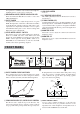
HOW TO CHANGE THE FADER UNIT Exchanging a ReX Fader Unit mounting unit, once release pull the fader upwards carefully. The ReX (Rapid Exchange) fader system has been designed to allow users to quickly exchange faders. By t Remove the cable connector from the fader unit carefully. following and adhering to the following directions and y Exchange the fader unit making sure to reconnect the advice you will be able to safely and easily exchange ReX cable connector unit correctly. type faders.
Changing the Direction of the Input Switch q Remove all knobs from the Battle Panel as illustrated. y Exchange the input switch unit making sure to reconnect the cable connector unit correctly. w Release the top panel as illustrated. e Caution should be exercised when opening the top u Replace the screws as removed in point 4. Check to panel so as to avoid any unnecessary damage to the make sure that you have correctly and securely panel unit or release system. replaced the input switch unit.
CONNECTION PGM1 INPUT TURN TABLE[VESTAX PDX-2000] CD PLAYER[VESTAX CDX-16] EFFECTER[VESTAX DPH-X1] OUTPUT GND OUTPUT OUTPUT PHONO1 LINE1 EFFECT SEND EFFECT RCV GND SERIAL NO.
SPECIFICATION NOMINAL INPUT MAXIMUM INPUT INPUT SECTION MIC (φ6.3 PHONE JACK) -50.0dBv -32.0dBv 3.3kΩ PHONO 1.2L /R (RCA PIN JACK) -46.0dBv -22.4dBv 56kΩ LINE 1.