Professional Mixing Controller OWNER'S MANUAL VESTAX CORPORATION VESTAX America VESTAX (Europe)Ltd.
CONGRATULATIONS! Thank you for purchasing the VESTAX PMC-25, Professional Mixing Controller. Please read this owner's manual carefully before you start to use your mixer, so that you will fully understand all of the special features and enjoy the full use of the product.
IMPORTANT SAFEGUARDS READ BEFORE OPERATING EQUIPMENT This product was designed and manufactured to meet strict quality and safety standards. There are, however, some installation and operation precautions which you should be particularly aware of. 1. Read instructions-All the safety and operating instructions should be read before the appliance is operated. 2. Retain instructions-The safety and operating instructions should be retained for future reference. 3.
16. Replacement Parts-When replacement parts are required, be sure the service technician has used replacement parts specified by the manufacturer or have the same characterristics as the original parts. Unauthorized substitutions may result in fire, electric shock or other hazards. 17. Safety Check-Upon completion of any service or repairs to product, ask the service technician to perfrom sefety checks to determine that the product is in proper operating condition. 18.
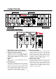
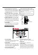
FUNCTIONS PROGRAM SECTION MASTER SECTION MIC SECTION MONITOR SECTION PROGRAM SECTION 2 1 3 9 8 7 10 6 5 4 5 MID (Isolator MID) ○ 1 INPUT SELECT (Input Select Switch) ○ Used to select input to be sent to each PGM channel. Cuts and boosts the mid frequency range. The level is flat when this knob is set at 12 o'clock. Mid frequency range is boosted up to +4dB when this knob is rotated clockwise. When the knob is rotated counter-clockwise, mid frequency range is cut off up to infinity level.
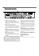
7 HI CUT (Fader type cut switch HI) ○ HOW TO REPLACE THE INPUT FADER When this volume is set to bottom position, high frequency range is cut of completely regardless of the position of the HI level control. The HI level control knob becomes active when this volume is set to maximum(top) position. ● Remove four screws, which hold the fader unit panel. the input fader unit, IF-25. ● Carefully remove the multi-cable connector from the fader unit. ● Insert the connector to the new fader unit.
HOW TO REPLACE THE CROSS FADER ● Remove four screws, which hold the fader unit panel. the cross fader unit, CF-R. ● Carefully remove the multi-cable connector from the fader unit. ● Insert the connector to the new fader unit. ● Remove Remove the multi-cable connector from fader unit. + + + + Remove four screws. MICROPHONE SECTION 17 INPUT (Mic Input Jack) ○ Input jack for the microphone. 18 LEVEL (Mic Level Volume) ○ Adjusts the input level of the microphone.
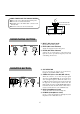
REAR PANEL SECTION 28 25 24 27 32 33 31 30 24 PHONO 1,2 [RCA PIN JACK] ○ 29 26 25 24 27 28 PA OUT (Balanced Output) [XLR MALE, 2 PIN HOT] ○ Connect turntables equipped with MM (Moving Magnet type) cartridge. The signal from the turntable is fed to the PGM channels when Phono input is selected. 29 ○ 25 LINE 1,2,3,4 [RCA PIN JACK] ○ Main output jacks. Connect to the input of the power amplifier or the master console with XLR 3 pin cable.
CONNECTION EXAMPLE Instruments connected to the PGM 2 Instruments connected to the PGM 1 ANALOG DISK TURNTABLE [Vestax PDX-a1S] CDPLAYER[Vestax CDX-35] ANALOG DISK TURNTABLE [Vestax PDX-a1S] CDPLAYER[Vestax CDX-35] OUT PUT OUT PUT GND TERMINAL LINE1 or LINE2 PHONO2 LINE3 or LINE4 GND TERMINAL PHONO1 GND GND PA OUT BOOTH OUT UNBALANCED INPUT POWER AMPLIFIRE [Vestax PT-X1000A] CHANNEL A MINI MAX CHANNEL B MINI MAX MONITOR SPEAKER PROTECT B.T.
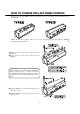
HOW TO CHANGE THE JACK PANEL POSITION The I/O jack panel of the PMC-25 can be placed either on the top or back side of the unit. Please refer to following Fig. Initially, the I/O panel is placed on the top-side. In case of changing the jack panel position to TYPE please use following instructions. ● Remove 5 pieces of silver screw, which secure the PANEL ①. ● Remove 5 pieces of silver screw, which secure the PANEL ②. CAUTION Please ensure use of the proper screwdriver (3mm Phillips type).
BLOCK DIAGRAM 10
SPECIFICATION NOMINAL INPUT LEVEL MAXMUM INPUT LEVEL INPEDANCE MIC(1/4 INCH PHONE JACK) -50dBv -20dBv 3.