
Specification

Rev. 12/5/2017 ASP, MANUAL
Copyright 2017 Vestil Manufacturing Corp. Page 5 of 6
Labeling diagram:
The step stand should always be labeled as shown in the diagram. Replace a label if it is missing
or not easily readable (severely faded or damaged, for example).
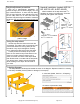
Height adjustment procedure:
Each leg is independently adjustable. To
extend the legs (and increase height), turn the
legs counterclockwise. To lower the step stand,
turn the legs clockwise. After adjusting the legs,
set the step stand on its feet and check its
levelness. Adjust the legs as needed to make the
stand level. Do not use the step stand unless it is
level.
A
B
B
A: Label 287 (Model, Serial no., & Capacity)
B: Label 213 (Hazards of Use)
Using the step stand:
Set the step stand as close to the work site
as possible. The rubber caps on the legs should
prevent the stand from moving while you use
the stand. If any cap is damaged or severely
worn, replace the caps before using the stand.
Center yourself on the steps as you climb
them. Do not reach far beyond the stand. If the
object you need to retrieve requires you to
reach, move the unit closer to the object. Both
feet should remain in contact with the step while
you retrieve items. Always remain flat-footed
while standing on the steps: Do not stand on
your toes!
Turn leg counterclockwise to increase
platform height
Handrail installation (models ASP-24-
HR, ASP-36-HR, & ASP-48-HR):
Attach handrails to the step stand with
5
/
16
”
hardware as shown in the diagrams. Cross bar
should lay flat against side of stand.
Handrail
Step stand
U-bolt (
5
/
16
”-18)
Fasteners:
5
/
16
” flat
washer,
5
/
16
” lock
washer,
5
/
16
”-18 hex
nut.
Bolt:
5
/
16
”-18 x 1”
Fasteners:
5
/
16
” lock washer
and
5
/
16
”-18 hex nut
U-bolt
Fasteners
Bolt + Fasteners
Cross
bar
Cross bar
flush with
side of stand