STEEL STORAGE SHED MODEL SHED-5932-F ASSEMBLY MANUAL VESTIL MANUFACTURING CORP. 2999 NORTH WAYNE STREET, P.O. BOX 507, ANGOLA, IN 46703 TELEPHONE: (260) 665-7586 -OR- TOLL FREE (800) 348-0868 FAX: (260) 665-1339 URL: WWW.VESTILMFG.COM EMAIL: SALES@VESTIL.COM NOTE: Compliance with regulations, codes, and/or standards actually incorporated into law enforced in the location where the product is used is exclusively the responsibility of the end user. Copyright 2012 Vestil Manufacturing Corp.
PRODUCT INTRODUCTION Thank you for purchasing a SHED-5932-F model Steel Storage Shed. Each shed includes the following features: panels protected from rust by zinc-plating; angled roofline to prevent rain accumulation on the roof; lockable door latch that incorporates a 5/16in. opening for a padlock (not included); and an open-floor design.
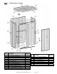
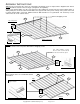
FIG. 1: Exploded parts diagram 17 Part no. Description 1L 1R 2L 2R 3 4 5R 20A 20B 20C 20D 20E 21A 21B 78in. x 30¼ in. rear wall panel 78in. x 30¼ in. rear wall panel (74.8 – 77.9)in. x 30.3in. side wall (74.8 – 77.9)in. x 30.3in. side wall 33.7in. x 30.3 in. roof panel 74.8in. x 27.9in. front panel 72.6in. x 30.3in. door 59.4in. front/back roof channel 59.4in. rear wall (top) channel 59.4in. rear wall (bottom) channel 59.4in. front wall (top) channel 59.4in. front wall (bottom) channel 30¼ in.
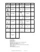
Hardware Item Description Quantity 10mm selftapping screw 16mm selftapping screw Hardware Item Description Quantity 120 Door latch 1 12 Door latch keeper 1 8 Sleeve anchor bolt 8 /16in. hex nut 8 Wall bracket 3 3mm x 10mm rivet 6 L-type channel cap 1 4mm x 10mm rivet 12 R-type channel cap 1 Anchor bolt bracket 8 Screw concealing cover 25 Reinforcing bracket 2 5 /16in. – ¾in.
ASSEMBLY INSTRUCTIONS: Step 1: Fasten rear panel 1R to panel 1L using 10mm self-tapping screws as depicted in the diagram below. Panels are shown with the outside surface facing up (corrugations face upwards). Connect top channel 20B to one side of the panels by either tapping the channel into place with a rubber mallet, or sliding it into place. Connect bottom channel 20C to the opposite side of the panels. The top of the panels is the side to which channel 20B is connected.
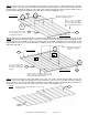
Step 3: Fasten channel pieces 21A and 21B to the side panel 2L. Orient panel 2L so that corrugations face upwards (outside surface is face up). Slide or tap channel 21B onto the bottom of panel 2L; then fasten the channel 32 to the panel with three (3) 10mm self-tapping screws. Slide or tap channel 21A into place, but do not fasten it with screws at this time. Attach channel 32 to the inside surface with three (3) 10mm self-tapping screws.
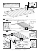
Channel Step 5B: First, tap or slide the channels 20A and 20A onto the top and bottom of the panel assembly; then lay the lip pieces 50 and 50 in place on each side of the panel assembly. Fasten the channels and lip pieces to the panels with 10mm self-tapping screws. Lip piece Roof Panel 20A 50 50 20A Step 6: Assemble the front wall.
Step 7: Fasten the door to the front wall assembly. (NOTE: The installation instructions that appear below show the door fastened to the right side of the door opening; the door can be installed on the left side as well. See “Alternative Door Installation” on p.12.) Fasten the door hinges to the door frame of the front wall assembly with 4mm x 10mm rivets. 2E Fasten the door latch to the door with 3mm x 10mm rivets.
Step 8: Fasten the front, rear, and side panels together. First fasten the side walls to the rear wall with 10mm screws; then fasten the front wall to the rest of the assembly with 10mm screws. Clamp the side panel 2L between jamb piece 41A and channel 22 by fastening 41A and 22 with six 16mm screws. 2L 22 10mm screw 41A 16mm screw 41A 2L 22 1R This symbol represents a 10mm self-tapping screw. Install a screw at each location where this symbol appears.
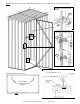
Step 9: Install the door latch keeper and wall-reinforcing brackets; then anchor the shed to a concrete surface. Installation of wall-reinforcing brackets 72 10mm screw Fasten the latch keeper to the door frame with either 10mm screws 71 -OR3mm x 10mm rivets 71 Anchor bolt and anchor bolt bracket installation Overhead, cut-away view of shed These symbols represent anchor bolt brackets Concrete DOOR Copyright 2012 Vestil Manufacturing Corp.
Step 10: Cover the ends of the wall-reinforcing channels in the doorway with the L-type and R-type channel caps. Copyright 2012 Vestil Manufacturing Corp.
Alternative Door Installation Flip the door over and position it in the door frame as desired. Align the frame wing of each hinge with the door jamb (41A) and drill holes in the jamb that match the holes in the wings. Before fastening the door to the jamb, tap the hinge pins out of the hinge knuckle and reinsert them from the top; then fasten the frame wings of the hinges to the door jamb with 10mm screws or 4mm x 10mm rivets.