A2 Inverter (0.75-30kW) Preface Version:1.78 Thank you very much for choosing high quality, multifunction, low-level noise and energy cost product by Isacon Power Control Tech. Co., Ltd --A2 series inverters. This manual contains the user setup, parameter setting, fault diagnosis, daily maintenance, and safety precautions. Please read this manual carefully before installing and operating the products. This manual is contained in the accessories of the productions.
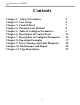
A2 Inverter (0.75-30kW) Contents Chapter 1. Safety Precautions Chapter 2. User Setup Chapter 3. Control Panel Chapter 4. Parameter Set Method Chapter 5. Table of Configure Parameters Chapter 6. Description of Control Ports Chapter 7. Description of Configure Parameters Chapter 8. Operation Examples Chapter 9. Error Message and Fault Diagnosis Chapter 10. Maintenance and Repair Chapter 11.
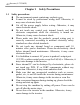
A2 Inverter (0.75-30kW) Chapter 1 1.1 Safety Precautions Safety precautions The environment cannot contain any explosive gas. It must be wired by professional wiring staff. Otherwise, it may cause electronic shock. Cut off the power supply before wiring. Otherwise, it may cause electronic shock. Do not touch any control port, internal boards, and their electronic components while the electricity is turned on. Otherwise, it may cause electronic shock.
A2 Inverter (0.75-30kW) 1.2 Package inspection A2 series inverter production undergoes a strictly qualification test. Please check the damage caused by the delivery and the type specification during package inspection. Accessories: 1 Inverter, 1 user manual. If anything is missing, please contact local dealer or Isacon’s custom service center.
A2 Inverter (0.75-30kW) Chapter 2 User Setup 2.1 Environment requirement No corrosive gas, vapour and oily dust. Without direct sunshine. No floating dust or mental particle. Air moisture 20%~90%. Vibration < 5.8m/s2(0.6g). No electromagnetic interference. Temperature:-10℃~50℃, make sure proper ventilation if the temperature is greater than 40℃. Without any inflammable or explosive gas, liquid and solid. Please use electric cabinet or remote operation in non-standard environment.
A2 Inverter (0.75-30kW) Wiring figure (single phase) Singlephase input FWD/STOP U L V N 0.
A2 Inverter (0.75-30kW) Wiring figure (three phase) R R three-phase input FWD/STOP S P T RUN REV/STOP REV RESET Multi speed D0 / Digital freq uency up Multi speed D1 / Digital freq uency down Multi speed D2 / External point mo ving enable U V D D0/+ DG Normally closed Lb 5k 1 Normally open Lk D1/D2/JOG GND The external analogsignal given 0-5V,0-10V,0-20mA external 2 1-5K 5V_IN 10V_ IN 0-20mA_IN GND 5V_OUT 5V_IN GND IM W 0.
A2 Inverter (0.75-30kW) Chapter 3 Button RUN STOP STOP RESET REV SET ▲▼ ◄► Potentiometer Control Panel Description Switch between run and stop state by single press. It has different meanings to push this button during different modes: 1.if the inverter is running, it would stop; 2. If a fault happens, the inverter would be reset; 3. If it is operated on menus, it returns to parent menu. Change the inverter’s direction. It also works during the runtime. Enter menu mode.
A2 Inverter (0.75-30kW) Content Description REV Anticlockwise rotation indicator. ANALOG SEGMENT PANEL Digital tube Analog input frequency indicator. Segment input frequency indicator. Panel input frequency indicator. Inverter runtime frequency. If inverter stops, it flashes. The display data is given by “Pn01” data. ERROR FWD Fault indicator. Clockwise rotation indicator. Chapter 4 Parameter Set Method 4.
A2 Inverter (0.
A2 Inverter (0.75-30kW) Item Description Modify by button ▲ or ▼ Range Modify by button ▲ or ▼ Pn 24 Pn 27 Multi-segment speed 5 frequency Multi-segment speed 6 frequency Multi-segment speed 7 frequency Point move frequency Pn 28 Choice of relay output 000.10 Hz— 400.00Hz 000.10 Hz— 400.00Hz 000.10 Hz— 400.00Hz 000.10 Hz— 400.
A2 Inverter (0.75-30kW) Chapter 6 Port name 12V OUT 5V OUT 5V IN 10V IN 20mA IN 5V Fout GND FWD REV RST D0 + D1 D2 JOG Lk Lb Lz Description of Control Ports Port Description 12V output, with maximum currency 200mA. 5V output, with maximum currency 50mA.
A2 Inverter (0.75-30kW) Pn 01 Chapter 7 Description of Configure Parameters Default display content:1——30000 RUN: 1 means it will display runtime frequency Otherwise, it displays motor’s synchronization speed. 2——30000 is motor synchronization speed STOP:it will display frequency given by external signal. Pn 02 Initial startup frequency by panel or other method Range:000.01Hz-400.00Hz,the initial panel data and external signal frequency during startup.
A2 Inverter (0.75-30kW) Pn 09 Deceleration time with range:000.01S-650.00S Decelerate time (from Pn10 to 0Hz). Pn 10 Maximum runtime frequency with range:000.10Hz-400.00Hz Maximum output frequency by inverter. Pn 11 Minimum runtime frequency with range:000.10Hz-400.00Hz If the frequency from command below this value, inverter will stop. It wouldn’t recover until command frequency up this value. Pn 12 Motor rating frequency with range:010.00Hz-400.00Hz It is used for modify the V/Fcurve.
A2 Inverter (0.75-30kW) Pn 15 Startup DC braking voltage:1V—100V By proper tuning of this parameter, motor can start normally from fully stop state without any difficult caused by motor’s free motion and rotate direction. Pn 16 Startup DC braking time:000.00S—650.00S DC braking time before motor startup to ensure that motor is started from fully stop state. Pn 17 Stop DC braking voltage:1V—100V Braking voltage during DC braking period to ensure that motor is fully stopped in brake time.
A2 Inverter (0.75-30kW) Pn 23 Multi-segment speed 4 frequency:000.10 Hz—400.00Hz Multi-segment speed mode 4-segment frequency Pn 24 Multi-segment speed 5 frequency:000.10 Hz—400.00Hz Multi-segment speed mode 5-segment frequency Pn 25 Multi-segment speed 6 frequency:000.10 Hz—400.00Hz Multi-segment speed mode 6-segment frequency Pn 26 Multi-segment speed 7 frequency:000.10 Hz—400.00Hz Multi-segment speed mode 7-segment frequency Pn 27 Point move frequency:000.10 Hz—400.
A2 Inverter (0.
A2 Inverter (0.75-30kW) Chapter 8 8.1 Operation by panel Operation Examples Pn 04 = 1(Command from panel),Pn 03 = 1(Frequency from potentiometer)。 Push button “RUN” on the panel, inverter starts up and running indicator is on. Push the button again, inverter would stop. 8.2 Operation by external signal Pn 04=2 (command from port “FWD/REV”) Pn 03=3 (frequency from port “5V”) 8.3 Multi-segment speed Pn 04=2(command from port “FWD/REV”) Pn 03=7(frequency from multi-segment 0-7) 8.
A2 Inverter (0.75-30kW) Chapter 9 Error Message and Fault Diagnosis 9.
A2 Inverter (0.
A2 Inverter (0.75-30kW) Chapter 10 Maintenance and Repair Due to the environmental influences such as temperature, humidity, dust, and vibration etc., and aging components, the inverter may fail at some time. So it needs periodic maintenance and repair. Notice: please check the following items before maintenance and repair. Otherwise, it may cause electronic shock. 1. Power source is cut off. 2. Indicator on panel is OFF. 3. Maintenance is performed by professionals. 10.
A2 Inverter (0.75-30kW) 10.2 Periodic maintenance The Inverter needs periodic maintenance every 1 or 3 months which depends on the runtime environment. Notice: Machine maintenance or component replacement must be performed by professionals. If any metal objects such screws or washer are left inside the machine, it would cause fatal damage to the inverter! Check items: 1、 Whether the control port screws are loose or not; 2、 Whether the main loop port i s loose or not.
A2 Inverter (0.75-30kW) 2. filter electrolytic capacitor Cause of damage: high environment temperature, frequently load change, long-time fully load. Criterion: liquid leak, wrong position of safety valve, capacity measurement. 10.4 Store of inverter Precautions for storing inverter: 1. It cannot be stored in high temperature, moist, dusty, metal dust, corrosive gas places. 2. It will speed up the capacitor aging during long-time store. Make sure that turn on inverter once every year.
A2 Inverter (0.75-30kW) Chapter 11 Type Description 11.1 Type description A2-xxxxB A2 is the vfd series, xxxx For power and voltage levels. B is Brake unit 11.2 Power description 1XXX 1: input 3phase 220V, output 3phase 220V 2XXX 2: input 1phase 220V, output 3phase 220V 3XXX 3: input 3phase 380V, output 3phase 380V 5XXX 5: input 1phase 220V, output 3phase 380V 6XXX 6: input 1phase 380V, output 3phase 380V Note: three phase input can also be.