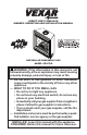
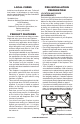
DIRECT-VENT FIREPLACE OWNER’S OPERATION AND INSTALLATION MANUAL NATURAL or propane/lp GAS Model CD36T-M WARNING: If the information in this manual is not followed exactly, a fire or explosion may result causing property damage, personal injury or loss of life. — Do not store or use gasoline or other flammable vapors and liquids in the vicinity of this or any other appliance. — WHAT TO DO IF YOU SMELL GAS • Do not try to light any appliance.
WARNING: Improper installation, adjustment, alteration, service or maintenance can cause injury or property damage. Refer to this manual for correct installation and operational procedures. For assistance or additional information consult a qualified installer, service agency or the gas supplier.
Safety WARNING: This product contains and/or generates chemicals known to the State of California to cause cancer or birth defects or other reproductive harm. IMPORTANT: Read this owner’s manual carefully and completely before trying to assemble, operate or service this fireplace. Improper use of this fireplace can cause serious injury or death from burns, fire, explosion, electrical shock and carbon monoxide poisoning.
Safety Continued Carefully supervise young children when they are in the room with fireplace. Keep the area around your fireplace clear of combustible materials, gasoline and other flammable vapor or liquids. Do not run fireplace where these are used or stored. 1. For propane/LP fireplace, do not place propane/LP supply tank(s) inside any structure. Locate propane/LP supply tank(s) outdoors. To prevent performance problems, do not use propane/LP fuel tank of less than 100 lbs. capacity. 2.
Local Codes Install and use fireplace with care. Follow all local codes. In the absence to local codes, use the current National Fuel Gas Code ANSI Z223.1/NFPA 54* (USA). *Available from: American National Standards Institute, Inc. 1430 Broadway New York, NY 10018 National Fire Protection Association, Inc.
Pre-Installation Preparation Continued • When locating termination cap, it is important to observe the minimum clearances shown in Figure 7, page 8. • If recessing into a wall, you can avoid extra framing by positioning your fireplace against an already existing framing member. • Do not recess termination cap into a wall or siding. • You may paint the termination cap with 450º F (232º C) heat-resistant paint to coordinate with the exterior finish.
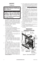
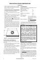
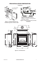
Pre-Installation Preparation Continued 2 - 2"x4" Vertical Double Stud 14 3/4" 21" TO CENTER OF TOP VENT 28 5/8" 14 3/4" TO NAILING FLANGES 12 1/4" TO OPENING 36" 56 3/4" 36 1/4" 14 3/4" Figure 4 - Framing Clearances for Installation Against an Exterior Wall These dimensions allow for 1" of clearance at the sides and back of fireplace. 0" clearance is also permitted at all sides if framed.
Pre-Installation Preparation Continued MANTEL CLEARANCES Figure 7 shows projected mantel depths at various heights above the top of the louver opening. Figure 8 shows the minimum allowable distances from various mantel components in relation to the both sides of the fireplace opening. 1 WARNING: When finishing appliance, do not overlap combustible materials onto the black front face.
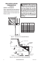
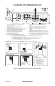
Location of Termination Cap N N D H V L E B C Fixed Closed F B Openable Fixed Closed V Openable V I V G B V B B J X V G G M A V K X V A G GAS METER RESTRICTED AREA V TERMINATION CAP X AIR SUPPLY INLET (TERMINATION PROHIBITED) A = clearance above grade, veranda, porch, deck, or balcony I = clearance to service regulator vent outlet [*72" (182.9 cm) [*12" (30.
Venting Installation NOTICE: Read these instructions completely before attempting installation. NOTICE: Failure to follow these instructions will void the warranty. These models are tested and approved for use with DESA/Vexar (direct-vent) pipe components and terminations. The venting system must terminate on the outside of the structure and can not be attached to a chimney or flue system serving a separate solid fuel or gas burning appliance. A direct-vent appliance must have its own venting system.
Venting Installation Continued INSTALLATION PLANNING There are two starter vent kits available for either a horizontal or a vertical installation: • CHVK-58 Corner Horizontal Vent Kit - Intended for corner or flush installations with less than 24" of horizontal distance to the termination. • CVVK-58 - Ceiling Vertical Vent Kit - Intended for a straight vertical installation through a ceiling with less than 9' to a roof termination.
Venting Installation Continued WARNING: Do not recess vent termination into any wall. This will cause a fire hazard. 6. Combustible Exterior Wall: For vinyl siding, stucco or wood exteriors, a siding standoff may be installed between vent cap and exterior wall. Siding standoff prevents excessive heat from damaging siding materials. Siding material must be cut to accommodate standoff. Bolt vent cap to standoff. Apply non-hardening mastic around outside edge of standoff.
Venting Installation Continued GROUND FLOOR INSTALLATION Recommended CHVK-58 Corner Horizontal Vent Kit: • Installation using cabinet surrounds • Through wall using square termination (up to 24" horizontal pipe) • Corner installation (Using one 6" vertical section, one 90° elbow and a maximum of 24" of horizontal pipe) Straight/ Adjustable Pipe 24" Max.
Venting Installation Continued HORIZONTAL VENT INSTALLATIONS USING MULTIPLE 90° ELBOWS The following configurations show the minimum vertical rise requirements for a horizontal system using two 90° elbows. 90° Elbow 90° Elbow Venting with Two 90° Elbows Horizontal (H)+ Vertical (V) Horizontal (H2) 7' Min. 8' Min. 9' Min. 10' Min. 11' Min. 13' Min.
Venting Installation Continued Installation for vertical termination Note: Vertical restrictor must be installed in all vertical installations. 1. Determine the route your vertical venting will take. If ceiling joists, roof rafters or other framing will obstruct the venting system, consider an offset (see Figure 19) to avoid cutting load bearing members.
Venting Installation Continued 5. Place flashing over pipe section(s) extending through roof. Secure base of flashing to roof and framing with roofing nails. Be sure roofing material overlaps top edge of flashing as shown in Figure 19, page 15. There must be a 1" clearance from the vent pipe to combustible materials. 6. Continue to add pipe sections until height of vent cap meets the minimum building code requirements described in Figure 9 on page 9.
Venting Installation Continued Note: Install a Firestop Plate FP-58 or a Firestop Thimble FTA-58 to maintain cleaance to combustible ceiling or insulating materials. Venting with Two 90° Elbows Vertical (V) Horizontal (H) 8' Min. 9' Min. 10' Min. 12' Min. 14' Min. 40' Min. 90° Elbow 6' Max 8' Max 10' Max 14' Max 18' Max 20' Max Note: Install a VR-58 vertical restrictor ring into inner pipe section prior to attaching vent termination cap.
Venting Installation Fireplace Installation Continued ELECTRICAL SUPPLY CONNECTION Number Description CAUTION: Disconnect the CVVK-58 Ceiling Vertical Vent Kit electrical power to the supply (Includes: 30° Offset Return, 7"-12" Adjustable Pipe, Flue Restrictor, circuit before attempting to conVertical High Wind Termination, nect or service this appliance.
Fireplace Installation Continued 5. Remove two screws and outer cover on left side of the outer cabinet. 6. Reinsert junction box retaining flange through slot now on left side and swing screw mounting tab back through notch as before. 7. Slide junction box down till mounting tab holes line up and replace inner retaining screw. 8. With junction box cover removed, pull end of 3-wire Romex supply line through universal strain relief bushing on cover (see Figure 26, page 18). 9.
Fireplace Installation Continued 6. While supporting speed control, secure control shaft with lock nut by pushing and turning lock nut with pliers clockwise until it is tight against front panel. Place control knob provided on shaft. 7. Turn on power to duplex outlet if previously turned off per the warning on page 19. 8. Plug in blower power cord. a. If your firebox is installed as a freestanding unit with an accessory mantel, determine whether power cord will exit left side or right side of firebox.
Fireplace Installation Continued 11. Peel off backing paper and stick supplied wiring diagram decal on firebox bottom approximately 12" in front of blower (see Figure 29, page 20). Wiring Diagrams CAUTION: Label all wires prior to disconnection when servicing controls. Wiring errors can cause improper and dangerous operation. Verify proper operation after servicing. Variable Fan Switch Off Fan Switch (N.O.) 1 Black 2 On 110/115 V.A.C.
Fireplace Installation Continued Installing optional wall Mount Switch - gwmS2 1. Connect one terminal of 25 ft. wire for wall switch to TPTH terminal on valve. Connect remaining wire terminal to TH terminal on valve. Make sure that wire terminals are in positions on unit as pictured in Figure 33. If wires are not connected as shown switch will not work. 2. Route 25 ft. wire through openings provided on the sides of burner system to a convenient location to mount your switch. 3.
Fireplace Installation Continued Check Gas Type Use proper gas type for the fireplace unit you are installing. If your gas supply is not correct, do not install fireplace. See retailer where you purchased fireplace for proper fireplace according to your gas type or to purchase gas conversion kit (see Accessories, page 39). Installing Gas Piping to Fireplace Location WARNING: A qualified service person must connect fireplace to gas supply. Follow all local codes.
Fireplace Installation Continued WARNING: Use pipe joint sealant that is resistant to liquid petroleum (LP) gas. We recommend that you install a sediment trap/drip leg in supply line as shown in Figure 38. Locate sediment trap/drip leg where it is within reach for cleaning. Install in piping system between fuel supply and fireplace. Locate sediment trap/drip leg where trapped matter is not likely to freeze. A sediment trap traps moisture and contaminants.
Fireplace Installation Equipment Shutoff Valve Gas Meter Continued 4. Check all joints of gas supply piping system. Apply noncorrosive leak detection fluid to all joints. Bubbles forming show a leak. Correct all leaks at once. 5. Reconnect fireplace and equipment shutoff valve to gas supply. Check reconnected fittings for leaks. Test Pressures Equal To or Less Than 1/2 PSIG (3.5 kPa) 1. Close equipment shutoff valve (see Figure 40). 2.
Fireplace Installation Continued WARNING: If fireplace has been running, turn off and unplug fireplace. Let cool before removing glass door or louvers. Removing Lower Louver Access Panel 1. Grasp lower louver panel and pull up until hanger brackets release from door pins (see Figure 43). 2. Swing louver panel out until it clears fireplace opening. 3. Pull entire panel out until bottom tabs are free of slot openings in lower face frame. WARNING: Handle glass door panel with care.
Fireplace Installation Continued 6. Remount new frame in reverse order by placing positioning tabs on the glass frame into slots in retaining bracket then swinging door into sealed position and locking two latches in place. 7. Replace top louver panel, and then lower louver panel. UNLOCK LOCK Glass Door Panel 4. Open bag of ember materials. 5. Break apart about quarter sized pieces and place a single layer along full length of ember tray to hide bottom edge of base log (see Figure 47). 6.
Variable Control Knob Piezo Ignitor T LO TH ON LO TPTH TP PILO OUT IN lighting instructions Figure 48 - Control Valve 1. STOP! Read the safety information above. 2. Open lower louver panel. 3. Turn off all electric power to fireplace. 4. Push in gas control knob slightly and turn clockwise to OFF. 5. Wait five (5) minutes to clear out any gas. Then smell for gas, including near the floor. If you smell gas, STOP! Follow “B” in the safety information above.
Operation Continued MANUAL LIGHTING PROCEDURE 1. Remove glass door (see Removing/Replacing Glass Door, page 25). 2. Follow steps 1 through 8 under Lighting Instructions, page 28. 3. Depress gas control knob and light pilot with match. 4. Keep gas control knob pressed in for 30 seconds after lighting pilot. After 30 seconds, release gas control knob. Follow steps 9 through 12 under Lighting Instructions, page 28. 5. Replace glass door (see Removing/Replacing Glass Door, page 25).
OperatiOn Continued 3. Set the desired room temperature by pressing the TEMP + or - buttons. 4. Press the POWER and LOCK buttons together to turn off the fireplace Note: Do not leave the hand-held remote in the AUTO mode close to the fireplace. The radiant heat from the fireplace will turn off the fireplace. Ideally, place the hand-held remote in the center of the room facing towards the fireplace. Note: Do not hold the hand-held remote for a long time.
Inspecting Burners Check pilot flame pattern and burner flame patterns often. pilot assembly The pilot assembly is factory preset for the proper flame height. Alterations may have occurred during shipping and handling. Call a qualified service person to readjust the pilot if necessary. The position and pattern of the pilot flames in relation to the sensing devices should be as shown in Figure 52.
Conversion Instructions Continued 7. Loosen set screw on main burner air shutter, rotate to fully open, and retighten set screw (see Figure 56). 8. Reposition burner with air shutter placed over orifice mount and replace two screws on rear log stand and two screws at pilot assembly.
Conversion Instructions Mounting Screws Continued Gas Control Conversion N LOT O F PI Rubber Gasket Identification Label Figure 59 - Installing Pressure Regulator Assembly I LO Cleaning and Maintenance H Mounting Screws O F Convert gas control by swapping out valve regulator portion of gas valve. 1. Using a Torx T20 or slotted screwdriver, remove and discard three mounting screws, pressure regulator tower, and diaphragm/spring components (see Figure 58). 2.
Cleaning and Maintenance Continued WARNING: Do not use abrasive cleaners as this may damage glass. Use a nonabrasive household glass cleaner to clean glass. Do not clean glass when hot. Glass must be cleaned periodically. During start up it is normal for condensation to form on the inside of the glass causing lint, dust and other airborne particles to cling to the glass surface. During initial start up a slight film may form on the glass due to paint curing.
Troubleshooting WARNING: Turn off heater and let cool before servicing. Only a qualified service person should service and repair heater. CAUTION: Never use a wire, needle or similar object to clean pilot. This can damage pilot unit. Note: All troubleshooting items are listed in order of operation. The two most common causes of a malfunctioning gas appliance are: 1. Loose wiring connections 2.
TROUBLESHOOTING OBSERVED PROBLEM Continued POSSIBLE CAUSE REMEDY Pilot lights but flame goes 1. Gas control knob not fully 1. Press in gas control knob out when control knob is pressed in fully released 2. Gas control knob not 2. After pilot lights, keep gas pressed in long enough control knob pressed in 30 seconds 3. Equipment shutoff valve 3. Fully open equipment shutnot fully open off valve 4. Pilot flame not touching 4.
TROUBLESHOOTING Continued WARNING: If you smell gas • Shut off gas supply. • Do not try to light any appliance. • Do not touch any electrical switch; do not use any phone in your building. • Immediately call your gas supplier from a neighbor’s phone. Follow the gas supplier’s instructions. • If you cannot reach your gas supplier, call the fire department. OBSERVED PROBLEM POSSIBLE CAUSE Glass soots REMEDY 1. Flame impingement on 1. Adjust log set so flame does logs not excessively impinge on it 2.
TROUBLESHOOTING Continued OBSERVED PROBLEM POSSIBLE CAUSE REMEDY Gas odor even when control 1. Gas leak. See Warning 1. Locate and correct all leaks (see knob is in OFF position statement on page 37 Checking Gas Connections, page 24) Gas odor during combustion 1. Gas leak. See Warning 1. Locate and correct all leaks (see statement on page 37 Checking Gas Connections, page 24) Dark residue on logs or inside 1. Improper log placement 1.
Service Hints When Gas Pressure Is Too Low • pilot will not stay lit • burners will have delayed ignition • fireplace will not produce specified heat • propane/LP gas supply might be low (propane/LP units only) You may feel your gas pressure is too low. If so, contact your local gas supplier. Technical Service You may have further questions about installation, operation, or troubleshooting. If so, contact DESA Heating, LLC at 1-866-672-6040.
Parts Fireplace Assembly for Model CD36T-M 1-4 1-3 6 1-2 7 1-1 4 12 11 5 10 14 18 15 3 16 2 9 13 17 19 8 40 www.desatech.
PARTS FIREPLACE ASSEMBLY FOR MODEL CD36T-M This list contains replaceable parts used in your fireplace. When ordering parts, follow the instructions listed under Replacement Parts on page 38 of this manual. KEY NO. PART NO.
parts BURNER ASSEMBLY FOR MODEL CD36T-M 3 20 4 5 16 8 2 15 1 14 10 7 6 12 18 42 11 9 19 www.desatech.
PARTS BURNER ASSEMBLY FOR MODEL CD36T-M This list contains replaceable parts used in your fireplace. When ordering parts, follow the instructions listed under Replacement Parts on page 38 of this manual. KEY NO. PART NO.
Warranty KEEP THIS WARRANTY Model (located on product or identification tag)______________________________ Serial No. (located on product or identification tag)___________________________ Date Purchased ___________________________ Keep receipt for warranty verification.