FL-10 Operation Manual CONTENTS General Description Specifications Unit Installation Transducer Installation Unit Operation Helpful Tips Trouble Shooting Chart About Transducer Beam Angles Other Vexilar Products Transducers Service and Support 2 3 4-5 6-9 10 - 15 16 17 18 - 19 20 - 21 22 - 22 24 Founded in 1960, Vexilar, Inc. has a long history of bringing revolutionary technology to the sport fishing industry.
GENERAL DESCRIPTION The FL-10 is a compact in-dash mounted flasher fish finder. Besides indicating depth, the unit also shows changes in bottom content and conditions. It can also discriminate between large underwater targets, such as fish, and smaller targets like baitfish and plankton. The unit transmits bursts of high frequency pulses, which are converted from electrical to mechanical energy by the transducer.
SPECIFICATIONS Operating Voltage: Current Draw: Power Output: Frequency: Resolution: Target Separation: Display Colors: Depth Scales: Weight: 10.5 - 15 Volts (12 Volts Nominal) .25 Amps 400 Watts (Peak to Peak) 200 kHz 525 Segments 2.65" Min. 3 - Red, Orange, and Green 0-20, 0-40, and 0-200’ Feet 2-1/2 Lbs. w/transducer Transducer Beam Angle: Puck Style - 12 Degree Transom Mount - 12 Degree Additional beam angle options are available.
UNIT INSTALLATION To install the unit refer to Figure 4. You must have a minimum 3-3/8" hole in your dash or panel. Also, within 12", you should dedicate space for a 3/8" hole for the control and decal. Make sure that you will have enough room behind the dash to accept the unit and control. The flasher unit and the control each needs at least 3" of depth. To mount the flasher unit, feed the transducer, power, and control cables through the larger hole and set the unit into place.
panel. Ideally you want the outside nut to be as close to the outer end of the shaft as possible. When the right spacing has been achieved tighten snugly into place. Make sure the inner shaft portion is rotated fully counter-clockwise and then place the larger rubber o-ring followed by the larger control knob onto the shaft. Using the provided wrench, tighten the knob down. Make sure that the white mark lines up with the OFF position on the decal.
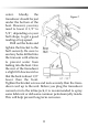
PUCK TRANSDUCER MOUNTING To attach a puck style transducer to a trolling motor use the large cable tie provided. Notice the slots in the transducer for this purpose. Locate the transducer on the bottom of the lower unit (figure 5). Run the cable up the shaft using smaller cable ties to hold it in position. Make sure that the motions of the trolling motor will not damage the cable.
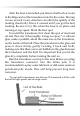
After the boat is launched, put about a half inch of water in the bilge and set the transducer into the the water. Moving it even an inch in any direction can effect the quality of the reading drastically. Move it around until you get the best reading. Be sure to try this when the boat is on plane and running at top speed. Mark the best spot. To install the transducer, first clean the spot of mud and oil and then dry it thoroughly.
TRANSOM TRANSDUCER MOUNTING Locate the transducer, and bracket hardware. This includes; 1 - Transducer 2 - Angle Brackets 4 - Bracket Screws 2 - Bracket Plates 4 - Nuts 4 - Mounting Screws First, attach the bracket to the transducer as shown in Figure 7. The flanges of the bracket normally point outward, away from the transducer. If mounting space is tight, you can reverse the angle brackets and face the flanges inward.
water. Ideally, the Figure 7 transducer should be just under the bottom of the boat. However, you may need to lower it 1/2” to 5/8”, depending on your hull shape, to get a good reading at top speed. Drill out the holes and tighten the bracket to the hull securely. Be sure to seal any holes drilled into the transom with silicone to prevent water from leaking into the boat. Give the rear of the transducer a slight tilt downward so that the back is about 1/8” lower than the front.
UNIT OPERATION To switch the FL-10 on, turn the larger control knob to the right. Turning the unit on also selects the depth range. The first setting covers zero to 20 feet. The second range covers 0 to 40 feet and the third range covers 0 to 200 feet. If the first setting shows only a mark at the zero position on the display, switch to a deeper range until you see the depth mark appear. Depth is read in the clockwise direction. Zero, or the water surface, is at the 12:00 position.
HOW TO FIND BOTTOM To read how deep it is, start at the zero mark (at the 12 o’clock position) and move clockwise. The bottom will be the largest mark other than the zero. The leading edge, the one closest to zero, will be where you read the depth. The width and color makeup of the bottom mark tells you what kind of bottom it is. The three-color display on the FL-10 will give you a lot more information than just depth. A color represents the strength of a signal.
Figure. J ZERO MARK SURFACE CLUTTER TRAILING EDGE BAIT FISH OR PLANKTON BOTTOM SIGNAL LEADING EDGE Read Depth Here Figure.
WEEDY BOTTOM In weedy conditions the bottom can be harder to determine. Figure K gives you an idea of what it may look like. To find the bottom in weeds it is important to keep the gain control low. If the gain is too high the bottom and the weeds will "run together" making it difficult to determine the actual depth. Some weed beds can be so dense that they will display as solid color, even at minimum gain. To find depth in these conditions it is often helpful to read the display backwards.
in the cone of sound we cannot readily identify them. For example, the green mark at seven feet in figure J could be a small piece of floating debris or a single small baitfish in the center of the cone. It could also be a large game fish at the very edge of the transducer cone. In the weeds, spotting fish is more difficult. Figure K shows a bottom at twelve feet. The weeds extend from the bottom up to about six feet. Notice the red mark at nine feet is labeled "possible fish".
Another type of noise is acoustical. This comes from the transducer picking up noise from turbulent water under the transducer. This can be due to a poor transducer mounting job or from engine exhaust or trolling motor thrust passing under it. Acoustical noise can be eliminated by adjusting the transducer’s location or position. HIGH SPEED OPERATION The FL-10 can accurately read depths at almost any boat speed. Here high speed is defined as any speed at or above the planning speed of the boat.
HELPFUL TIPS WHERE TO SET THE GAIN CONTROL Set the gain control so as to get a strong bottom mark. If you don’t see a bottom mark, switch to a deeper range setting, then turn the gain up until the bottom appears. Good bottom marks will show all three colors. The leading edge of the bottom echo should show a solid red band bleeding into orange. The trailing edge of the bottom mark will bleed from orange into green.
TROUBLE SHOOTING CHART Symptom Possible Cause Unit is turned on, but no display and motor is not running. Check for bad connections, proper hook up polarity, and make sure you have a good, fully charged, battery. Unit is turned on and the motor is running, but there is no display. Supply voltage too low. The unit will show no display if the voltage is below 10 volts. Check while unit is running. Unit runs well for a short time, then lights fade out or unit quits. Low battery or bad connection.
ABOUT TRANSDUCER BEAM ANGLES Beam angle has a large effect on the performance of your depth finder. There is more to it than simply area of coverage. The correct beam angle to use depends entirely on what you are trying to do with your sonar. If you are fishing for suspended fish then you probably would be very pleased with the performance of a 19º. However, if you were going after fish that are hanging right on the bottom, along a steep drop-off in very deep water, you would have better results with a 9º.
much more powerful than a wide beam transducer. This is because you are putting that same amount of power into a smaller area. This can be an advantage if you are fishing in deep water or a detriment if you are fishing shallow. A narrow beam transducer can be overpowering in shallow water. The FL-10 In-Dash comes standard with the 12 degree angle. This beam angle that works well in most applications. You can purchase optional transducers, for more specialized applications, with different beam angles.
More Depth Finders From Vexilar The EDGE2 Model LC-507 The Edge, LC-507, is an amazing depth sounder. It is unique in that it is like having two totally different sonar systems in one unit. It comes with two transducers, a 107 kHz, 38 degree, and a 400 kHz, 10 degree. The idea is that you mount the transducers right next to each other and compare the two different views directly on the split screen. You can also run either beam at full screen. Speed, temp, and voltage sensors are included.
The CLC-200 Five-Color LCD The CLC-200 is an affordable five-color liquid crystal depth/fish finder. This ultracompact unit is available in a super portable Boundary Waters version (shown) or in a standard gimbal mount setup complete with a Pro Mount removable swivel bracket. The LPS-1 Handheld Depth Finder The LPS-1 is a simple to use handheld digital depth finder. Use it for fishing, ice fishing, canoeing, backpacking, and scuba diving. Runs on one 9-volt battery.
Transducers and Accessories TB0044 - 19° transom mount high Speed Transducer. Comes with the mounting bracket and 25 feet of cable. TB0030 - 9° transom mount high speed transducer. Comes with the mounting bracket and 25 feet of cable. TB0084 - 12° transom mount high speed transducer. Comes with the mounting bracket and 25 feet of cable. TB0045 - Dual beam 9/19°transom mount high speed transducer. Comes with the mounting bracket and 25 feet of cable.
TB0032 - Dual Beam 9/19° puck transducer. for mounting on a electric trolling motor, in-hull mounting, portable use, or ice fishing. Comes with 25 feet of cable. Built-in switch box must be mounted within 3 feet of the depth finder. "S" CABLE - The S-Cable (short for Suppression Cable) is used to reduce the output power of the FL-10. This can often help clear up readings in shallow or cluttered waters.
Service and Support If you find that you need help please contact us. Have ready the model number and, if possible, the serial number of your product. Be sure to read the Tips and Trouble Shooting sections first. Address Vexilar, Inc. 200 W. 88th St. Minneapolis, MN, 55420-2752 Telephone (952) 884-5291 (8 am to 5 pm M-F Central Time) Fax (952) 884-5292 Email service@vexilar.com Web Site www.vexilar.com The Vexilar web site contains a wealth of helpful information.