FL-18 Owner’s Manual CONTENTS General Description Specifications Unit Installation Power Connection Transducer Installation Operation Typical Indications Frequently Asked Questions Maintenance Transducer Beam Angle Chart Trouble Shooting Chart Accessories and Other Products Transducers Service and Support 2 3 4 4 5-8 9 - 11 12 - 16 17 - 20 21 22 23 24 - 26 27 - 28 29 Founded in 1960, Vexilar, Inc. has a long history of bringing revolutionary technology to the sport fishing industry.
GENERAL DESCRIPTION The FL-18 is a compact and lightweight depth sounder designed for serious anglers. Besides indicating depth, the unit also shows changes in bottom content and conditions. It can also discriminate between large underwater targets, such as fish, and smaller targets such as bait fish and plankton. The split-screen zoom feature provides very high display resolution within the bottom six feet of the depth.
SPECIFICATIONS Operating Voltage: Current Draw: Power Output: Frequency: Resolution: Target Separation: Display Colors: Dimensions: Weight: 10.5 - 15 Volts (12 Volts Nominal) 275mA 400 Watts (Peak to Peak) 200 kHz 525 Lines of Resolution 2.65" Min. 3 - Red, Orange, and Green 4.4"H x 6"W x 2.5"D 1.1 Lbs.
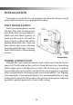
INSTALLATION To be able to use the FL-18, you must provide the unit with power and mount the transducer in an appropriate location. UNIT INSTALLATION Find a convenient place to mount the unit. This may include a boat seat, deck, dash, or a portable case. Make sure that there is plenty of room for the unit to tilt and/or swivel freely without the cables binding behind the unit. Once you have found a spot, remove the unit from the gimbal bracket. Securely attach the bracket to the mounting surface.
TRANSDUCER INSTALLATION There are three basic types of transducers to consider: High Speed, Puck Style, and the Ice-Ducer System. HIGH SPEED TRANSDUCERS When choosing an area to mount the transducer, keep in mind that you need clear water flow across the face of the transducer to insure a clear reading at all speeds. Try to stay away from rivets, ribs, or strakes that would be just in front of the transducer. They can disturb the water and scramble the reading.
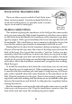
PUCK STYLE TRANSDUCERS There are three ways in which a Puck Style transducer can be mounted. It can be mounted In-Hull, on an electric trolling motor, or portable (with a suction cup or on an arm of some type). Puck Style Transducer IN-HULL MOUNTING This method of gluing the transducer to the hull gets the same results as if you were using the High Speed transducer, only there are no holes to drill in the boat and there is no transducer on the transom to get damaged by impact.
TROLLING MOTOR MOUNTING To attach a Puck Style transducer to a trolling motor, use the large cable tie provided*. Notice the slots in the transducer for this purpose. Locate the transducer on the bottom of the lower unit as in figure F. Run the cable up the shaft using cable ties to hold it in position. Make sure that the movement of the trolling motor will Figure F not damage the cable. Plug the transducer connector into the back of the unit and screw the retaining ring down tight.
THE ICE-DUCER™ SYSTEM* The Ice-Ducer system provides a quick and easy way to set up the transducer for ice fishing. All of the adjustments needed to find the true perpendicular point are done automatically. To use the Ice-Ducer, simply adjust the transducer to the desired depth and drop the assembly in the ice hole. There are three main components to the Ice-Ducer system. They include the transducer, float, and the stop. The transducer comes assembled with the connector already installed.
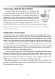
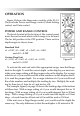
OPERATION Figure H shows the three main controls of the FL-18. They include Power and Range control, Mode Setting control, and Gain control. POWER AND RANGE CONTROL The knob located at the bottom of the control panel turns the unit on and selects which range is to be used. The far left position is the OFF position. There are five depth ranges to choose from.
MODE CONTROL The Mode control selects the FL-18s output power level and zoom view. The Normal position will be the setting that is used most often. With the Normal setting, the FL-18 operates in the standard flasher mode with normal (high) power. The depth is read using the outer white scale on the display. LP, or Low Power, Mode is used for shallow water conditions. Generally depths of 15 feet or less. The FL-18s LP Mode output power level is approximately 50% less than the Normal Mode.
the full view side, but will remain fixed at the zero mark on the zoom view. Auto Zoom works best while moving very slowly or while you are stationary, such as ice fishing. Bottom Lock works best for trolling or moving at higher speeds. Both the Auto Zoom and Bottom Lock features are available when in Low Power or the Normal Modes. GAIN CONTROL The knob located at the top of the control panel is the gain control. This controls the amount of signal that you see on the display.
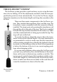
TYPICAL INDICATIONS Zero Signal Trailing Edge Bottom Signal Leading Edge Read Depth Here Fish Fig. J Bait The three-colors of the FL-18’s display represents the strength of a signal. A red color indicates a strong signal, an orange color indicates a medium strength signal, and green represents a weak signal. The colors will combine to indicate objects, such as bottom echoes, structure, fish, and plankton.
Gain about half way and continue clicking the range switch to the right until it does show a bottom signal. Once you find the bottom signal, line up the leading edge with the closest white depth mark on the scale. Refer to figure J and K. Multiply this reading by the depth range setting. SEEING FISH Refer, again, to figure J. If the range setting is X1 then the fish is just over a foot above the bottom. We know it’s a fish because it is a significant target that is not attached to the bottom.
the red target at 7 feet is marked "possible fish". We cannot say that it is a definite fish because the weeds around it are dense enough to give a red signal themselves. Again, keep the gain as low as you can for reading in the weeds. This would be a good situation to use the Low Power Mode. Switch the Mode to LP and turn the gain up until you get a clear reading of the bottom, but not so high as you can see all of the weed clutter.
Fish A Fish B Fig. M Bottom (Full View) Fish A Second Echo Fish B Third Echo Bottom (Zoom View) visible on both displays because it is less than 6 feet from the bottom. However, Fish B and the bait are more than six feet from the bottom so they do not appear in the zoom view. Figure M shows a typical open water situation where the FL-18 is set to the Bottom Lock mode. It is important to note that when the depth exceeds the selected range, the Bottom Lock feature will lose its lock on the bottom.
ICE FISHING Ice fishing brings out the best in the FL-18. The stable platform of ice lets you concentrate on your bait and the fish around it. The bottom becomes less important because it never changes. The only movement on the display is of your bait and fish. Unlike open water use, the direction in which the transducer is pointed is very critical. You want your bait to be located in the dead center of the cone of sound.
FREQUENTLY ASKED QUESTIONS Where Should The Gain Control Be Set? Generally, the gain should be set to give you a good reading of the bottom. This would mean a red leading edge. A basic rule to use is one number of gain for every 10 feet of depth. Although you will want to finetune this setting with the current conditions in mind. For ice fishing, you want set your gain level by the appearance of your bait. With your bait down at the fishing depth, adjust the gain to make your bait appear as a green signal.
instructions that come with the battery. To get the most out of it, follow these simple tips; Charge the battery as soon as possible after each use or, if it's cold, as soon as it reaches room temperature. Do not overcharge or under charge the battery. If possible, use a battery charger that has an automatic shut-off feature. A battery should be stored, fully charged, in a cool place. Charge it every month or two when in storage to make sure it maintains a full charge.
What Do The Colors In The Bottom Light Mean? Besides depth the bottom light can give you a lot of information. The width and color content of the bottom signal can tell you what type of bottom it is. Ice fisherman can look for movement of color in the bottom signal. If you see a red line move through the orange or green part of the bottom signal, it's probably a fish close to the bottom and away from the center point of the beam angle.
nal, the FL-18 will think that the depth has changed and lock on the new signal instead of the real bottom. This appears to you as the target suddenly disappearing from the display. What has happened is that the Bottom Lock has locked onto the new strong signal. Instead of zooming from the bottom up, you are zooming from the new signal up. When the target goes away, the FL-18 will re-lock the correct bottom. This makes for a “jumpy” display that is difficult to interpret.
MAINTENANCE Permanent Mount With permanent mount applications, the power cord is left connected to the source, the transducer is not easily removed, and the gimbal bracket is screwed to the seat, deck, or dash. Under these conditions maintenance is very simple because nothing changes once the unit is installed. Because of this, problems can sneak up on you if you're not careful. The unit should be removed from the bracket whenever the boat is parked to guard against theft.
TRANSDUCER BEAM ANGLES VERSES DIAMETER OF COVERAGE AND PERFORMANCE Beam angle has a large effect on the performance of your depth finder. There is 10’ 1.6’ 2.2’ 3.4’ more to it than simply area of coverage. The 20’ 3.2’ 4.3’ 6.7’ correct beam angle to use depends entirely 30’ 4.7’ 6.3’ 10.0’ on what you are trying to do with your 40’ 6.3’ 8.4’ 13.4’ sonar. If you are fishing for suspended fish 50’ 7.9’ 10.6’ 16.7’ 60’ 9.4’ 12.6’ 20.8’ then you probably would be very pleased 70’ 11.0’ 14.7’ 23.
TROUBLE SHOOTING CHART Symptom Possible Cause Unit is turned on, but no display and motor is not running. Check for bad connections, proper hook up polarity, and make sure you have a good, fully charged, battery. Unit is turned on and the motor is running, but there is no display. Battery voltage too low. The unit will show no display if the voltage is below 10 volts. Check while unit is running. Unit runs well for a short time, then lights fade out or unit quits. Bad battery or connection.
FL-18 ACCESSORIES CARRYING CASE The unique P-160 Porta Case holds your Vexilar FLSeries or other manufacturer's sonar or GPS. It has space for your transducer, a rechargeable battery, and the Vexilar Battery Status Indicator. Just set it down on the ice or boat seat, position the transducer and turn on your flasher. The round base is just the right size to fit down inside a standard 5 gallon bucket. ECONOMY CARRYING CASE The P-100 carrying case is simple, sturdy, and inexpensive.
FLEXIBLE NIGHT LIGHT The flexible night light simply attaches to the Porta Case or other type of case to get light where it is needed. Just attach with the wing nut provided and hook up the battery clips. Extra bulb is included. PROMOUNT The ProMount is a releasable swival mount designed to hold marine electronics such as depth finders, GPS systems, and marine radios. Includes hole covering gasket and mounting hardware. MAG SHIELD The Mag Shield magnifies the display of any Vexilar FL-Series flasher.
The CLC-200 Five-Color LCD The CLC-200 is a five-color LCD depth finder with great multi-colored resolution at an affordable price. It’s available in either the popular Boundary Waters portable version (shown) or with a releasable swival ProMount mounting system. The FL-10 In-Dash Color Flasher The FL-10 is designed to fit in the standard in-dash mounting hole in your boat. It’s super bright and has an exclusive flat display with a very wide viewing angle.
Transducers and Accessories TB0044 - 19° Transom Mount High Speed Transducer. Comes with the Mounting Bracket and 25 Feet of Cable. TK184 - Complete Mounting Kit. Comes with TB0084 Transducer, FL Power Cord, Unit Mounting Bracket, and all the Hardware You Need to do the Job Right. TB0084 - 12° Transom Mount High Speed Transducer. Comes with the Mounting Bracket and 25 Feet of Cable. TB0030 - 9° Transom Mount High Speed Transducer. Comes with the Mounting Bracket and 25 Feet of Cable.
TB0087 - 12° Puck Transducer. For Mounting on a Electric Trolling Motor, In-Hull Mounting, Portable Use, or Ice Fishing. Comes with 25 Feet of Cable. TB0032 - Dual Beam 9/19° Puck Transducer. For Mounting on a Electric Trolling Motor, In-Hull Mounting, Portable Use, or Ice Fishing. Comes with 25 Feet of Cable. Built-In Switch Box must be Mounted within 3 Feet of the Depth Finder. TB0050 - 19° Ice-Ducer. Self Leveling and Floats in the Ice Hole.
Service and Support If you find that you need help please contact us. Have ready the model number and, if possible, the serial number of your product. Be sure to read the Frequently Asked Question and Trouble Shooting sections first. Address Vexilar, Inc. 200 W. 88th St. Minneapolis, MN, 55420-2752 Telephone (952) 884-5291 Fax (952) 884-5292 Email service@vexilar.com Web Site www.vexilar.
Notes 30