Vexilar FL Series Sonar/Fish Finders Owners Manual For Models: FL-8SE | FL-12 | FL-18 | FL-20 | FL-22HD Contents Vexilar — Pioneers in Marine Electronics About Flashers Flasher Operation Basic Use About the Display Range Control FL-8se Range Control FL-18 Range Control FL-12/20 Range Control FL-22HD Setting the Gain Interference Rejection Low Power Mode Auto Zoom Bottom Lock Low Battery Indicator Understanding Zoom FL-18 Zoom AutoZoom FL-20 Zoom AutoZoom FL-22 Zoom AutoZoom Night Mode Boat Use Navigation Bo
Vex i l a r — Pio neers i n Mar i n e E l ec t r o nic s Established in 1960, Vexilar, Inc. has been a leading innovator of marine electronics in the sport fishing industry for over 50 years.
Abo u t F l a s h er s How Sonar Works SONAR stands for SOund NAvigation Ranging. Sound travels through fresh water at a speed of approximately 4920 feet per second. A sonar device (depth finder/fish finder) measures the amount of time a burst of energy takes to travel to the bottom and return to the transducer. This time variation is then displayed on the readout of your sonar. When the depth gets deeper, the time of travel for the sound increases.
Fla sh e r O p er atio n Basic Use The Vexilar FL series color flashers are great tools for open water and ice fishing. Once you learn to understand the color display, you can apply this knowledge to greatly increase your awareness of what’s under the water. FL S eries F l ashers C an B e U sed F or : • • • • • • Determining the current depth at any boat speed. Locating fish-holding underwater structure. Determining the bottom hardness and transition lines. Penetrating thick vegetation to see what’s below.
About the Display The FL series flasher display consists of three colors (marks) which appear at various positions on the screen. Understanding what the colors mean, and the position and size of the colored marks, is the key to being able to interpret the information correctly. RED = Strong Strength Signals. Strong signals are generally produced by significant underwater objects, such as the bottom, heavy vegetation, and large fish.
Setting the Range FL-8SE The FL-8SE has six depth ranges in two groups, Shallow and Deep. The Shallow group includes Zero to 20’, 40’, and 80’. The deep group includes Zero to 30’, 60’, and 120’. To interpret depth, you multiply the displayed reading by the range multiplier. Deep Range Group Look at the inner scale and the right-hand multipliers in yellow Shallow Range Group Look at the outer scale and the left-hand multipliers in white S hallow G roup • S-1 = Zero to 20 feet.
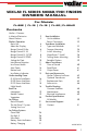
Setting the Range FL-18 The FL-18 has 5 depth ranges. Zero to 20’, 40’, 60’, 80’, and 200’. To interpret depth, you multiply the displayed reading by the range multiplier. Normal mode selected In normal mode, read the outer white scale and multiply by the range setting. Here, the range is set to “x1”. Bottom is at 15 feet, a fish is at 12 feet, and there is a weak signal at 10 feet.
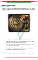
Setting the Range FL-12 and FL-20 Both the FL-12 and FL-20 have five depth ranges consisting of Zero to 20’, 40’, 60’, 80’, and 200’. To read depth, you match the color of the range selected with the depth scale of the same color. Match the color in which the range knob is pointing to the same colored depth scale. Here, the range is set to 20 feet, which is yellow. To read depth, look at the yellow scale on the flasher display.
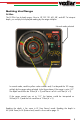
Setting the Range FL-22HD The FL-22HD has 6 depth ranges. Zero to 10’, 20’, 30’, 40’, 50’, and 60’. To interpret depth, you multiply the displayed reading by the range multiplier. Normal mode selected In normal mode, read the yellow scale numbers and, if set beyond the 10’ range, multiply by the range setting selected. In the figure above, if the range is set to “x2”. The depth would then be 16 feet (8’ x 2), and there is a fish is at 8 feet (4’ x 2).
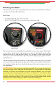
Setting the Gain Gain functions are the same on all models. However, the FL-8se and FL-18 have a different scale than the FL-12, FL-20 and FL-22HD. G ain S cale • The FL-8se and FL-18 use a zero to ten scale. • The FL-12, FL-20 and FL-22HD use a Minimum to Maximum scale. FL-8se / FL-18 Gain Control FL-12, FL-20 & FL-22 HD Gain Control Gain controls the amount of amplification applied to the return sonar signal. Think of gain as your volume control. You turn up the gain to see more of what’s below.
Interference Rejection The purpose of interference rejection is to reduce cross-talk interference from other nearby depth sounders. This can be very helpful if you have another sounder mounted on your boat running at the same frequency as your flasher. It is also helpful when other fishermen are running sounders operating at the same frequency as your flasher nearby. Cross-talk interference occurs when the signals sent from one depth sounder are received by another.
FL-8SE and FL-12 Interference Rejection comes on automatically when you power up the flasher. You can turn it off by pressing on the gain control. If interference from another sounder is present on the display, press this button repeatedly until it goes away or is reduced as much as possible. FL-18, FL-20 and FL-22 HD Interference Rejection comes on automatically when you power up the flasher.
Add i t i o n a l Feat u res Low Power Mode ( Not Available on FL-8SE ) Low Power Mode, or LP Mode, reduces the output power of your flasher. It is useful for situations where the gain cannot be turned down enough in Normal Mode. Use the Low Power Mode only when you need to. Usually, you’ll use it in only very shallow or very weedy conditions. FL-18 Activate the Low Power Mode (LP) by switching the Mode control to the left. The range can be set at any position.
Auto Zoom ( FL-18, FL-20, & FL-22HD Only ) Auto Zoom (AZ) puts the flasher into a split-screen view, with the complete water column on the right and a magnified view from the bottom on the left. When you switch to Auto Zoom Mode, the flasher automatically selects the magnified bottom view for you. However, you do need to have the flasher set to a depth range in which the bottom is in view. FL-18 Activate Auto Zoom by switching the Mode control to the AZ selection on the right or the left.
Bottom Lock ( FL-18 & FL-22HD Only ) Bottom Lock (BL) works the same as Auto Zoom, except the flasher continuously updates the position of the bottom in the magnified view. This can be helpful in a boat that is moving over varying depths or is riding in heavy waves. Bottom Lock will keep the bottom reading lined up correctly with the zero mark on the Zoom scale. This allows you to see objects which are very close to the bottom, even though the depth may be changing rapidly.
Understanding the Zoom Modes When Auto Zoom (AZ) or Bottom Lock (BL) is active, the display is divided into two halves. When reading depths always use the inner scale on the right side. When the range is set to 20, read this scale “as is”. When the range is set to 40, double the reading. If set to 60, triple the reading. FL-18 - Auto Zoom THE LEFT HALF represents the zoom view. From the bottom up to six feet. Read the distance from the bottom using the inner yellow scale.
FL-20 - Auto Zoom THE LEFT HALF represents the zoom view. From the bottom up to six (or 12) feet. Read the distance from the bottom using the large white scale. THE RIGHT HALF represents the entire water column, from the transducer to the bottom. Read the depth using the inner red/white scale. You interpret the depth by multipling the indicated value on the red/ white scale by the multiplying factor here. The Zoom scale reads in the Bottom opposite direction as the full view scale.
FL-22HD - Auto Zoom THE LEFT HALF represents the zoom view. From the bottom up to six feet. Read the distance from the bottom using the outer white scale. THE RIGHT HALF represents the entire water column, from the water surface to the bottom. Read the depth using the inner white scale. The zoom scale reads in the Bottom opposite direction as the full view scale. The bottom will always be at the 7 o’clock position. Objects will appear above this point.
Boat U s e Navigation The Vexilar FL series of flashers are great tools for navigation while boating. The instantaneous readings offer the ability to identify depth changes quickly. Here are some tips to help you navigate safely. CAUTION: • Be sure you know which range you have selected. If you think you have the flasher set to a deeper range than what it actually is, you may run aground unexpectedly.
Vegetation The Vexilar FL series flashers are exceptional when it comes to reading inside vegetation. With proper transducer choice, the colors will allow you to differentiate vegetation from the bottom. Experience will even allow you to identify fish inside heavy vegetation. T ips for R eading in V egetation • Narrow transducer cone angles will perform better than wide cone angles. • Keep the gain setting very low. Too much gain will make readings difficult.
Ice F i s h ing Basic Principles The FL series color flashers offer distinct advantages over traditional depth sounders for the sport of ice fishing. This unique style of fishing offers a stable platform to fish from. Because everything is so stable, the only movements below are that of fish. Additionally, the conditions allow you to drop your bait directly down into the center of the transducer’s cone of sound. This allows you to be able to see your bait and the fish on the display at the same time.
Ice Fishing Transducer Vexilar ice fishing systems include a special type of transducer patented in 1997 called the Ice-Ducer®. This transducer style is designed specifically for the ice fishing application. The Ice-Ducer® works off the “plumb-bob” theory. When suspended by the cable, the transducer cone is perfectly aligned to point straight down. I ce -D ucer ® C omponents Stopper - The stopper sets the depth of the transducer.
Seeing Your Lure The key to ice fishing success when using a Vexilar ice fishing system is the ability to see your fishing lure and it’s relationship to the bottom, structure, and fish. Ice fishing with a Vexilar allows you to present your lure to the fish. You see the fish on the display and you raise your lure so it is right above the fish on the display. If the fish is hungry, it will bite. If not, it will react in some way to your presentation, such as with disinterest or fear.
I ce F i sh ing S y s t ems The Genz Pack The Genz Pack offers a great value in an affordable ice fishing pack. It includes all of the basic components needed to ice fish with a Vexilar FL series flasher immediately. A key factor of the Genz Pack is that it fits on top of a five gallon bucket (not included). Carry Case The Genz “Blue Box” is a two-piece system made from a high density polyethylene.
Battery Compartment To remove the battery, remove the four rear section screws. Transducer Holder Store the transducer in the special holder above the battery. The holder is designed to accept all styles of Ice-Ducers. Easy Charge Jack Charge the battery here. You do not need to disconnect the battery connections while charging Cable Storage Stuff extra cable into the storage compartment Eye-Bolt under the flasher unit. Insert the transducer support eye-bolt here.
The Pro Pack II The Pro Pack II offers everything needed to begin ice fishing with a Vexilar color flasher, plus some extra add-ons to make the system more complete. Battery Status Indicator Shows the current level of charge in the battery. See page 30 for instructions. Battery and Charger 12 Volt / 9 Amp battery with 1 amp digital automatic charger. FL-12 Shown Tackle Box The Vexilar tackle box fits into a convenient location here.
Battery Compartment To remove the battery, remove the flasher from the carrying case, then the transducer holder by removing the two mounting screws. Transducer Holder Store the transducer in the special holder above the battery. The holder is designed to accept all styles of Ice-Ducers. Accessories Use the pre-drilled holes for Vexilar addon accessories, such as the FlexLight, or Tri-Beam Transducer. See pages 45 - 47. Eye-Bolt Insert the transducer support eye-bolt here, the pack’s front or far side.
The Ultra Pack The Ultra Pack is rugged and packed with features. The Ultra Pack includes a D-130 Battery Status Indicator, tackle box, remote accessory posts, a strong float holding handle, four rod holder mounting locations, an enclosed battery compartment and master power switch. Float Holder Store the Ice-Ducer float here. Rod Holder Adjustable angle and fits into four mounting locations; either side, front and back. Enclosed Battery Compartment The battery is enclosed within the base here.
Accessories Tackle Box The Vexilar tackle box fits into an easy access holder on the back of your Ultra Pack. Use the pre-drilled holes for Vexilar addon accessories, such as the FlexLight or Tri-Beam Transducer switch. See page 44 - 47 Eye-Bolt Insert the transducer support eye-bolt here, on the opposite side, or in the front. Be sure to remove the float from the transducer cable when using the eye-bolt. Non-Slip Bottom The non-slip bottom fits into a standard fivegallon bucket for convenient storage.
Battery Status Indicators D-130 Digital Status Indicator A unique battery fuel guage that recognizes both the discharge and charge cycle of your battery. It will sense the current charging condition of the battery, display the percentage of remaining capacity and display a charge trend arrow... ( or ).
Battery Charging CHARGE AFTER EACH USE 1 Amp Digital Automatic Charger (model V-410 / 1 Amp) 1 Allow the battery to warm up before charging. This makes it easier for the charger to charge the battery and the battery is more accepting of a charge. 2 Plug the charger into a wall outlet, verify that it is operating by noting the illuminated GREEN light. 3. Connect the charger to the Easy Charge Jack attached to the unit.
Boat I n s ta l l at io n Mounting the Flasher Unit Take a few minutes to plan your installation. The unit should be mounted in a location where it will be readily visible yet out of the way of traffic. The mounting surface should be fairly flat. Be sure to allow clearance for the cables at the rear of the unit while it tilts and swivels. The unit is weather-proof, not waterproof, so try not to mount it in a location where it will be exposed to the extreme forces of wave impact during severe conditions.
Tra n sd uc er I ns tallat i on Transducer Types and Mounting Methods There are several different transducer styles used for the various mounting options available to you. Choose the style which best meets the needs for your mounting application. T ransducer T ypes • High-Speed Transom: This style is designed to be mounted externally on the transom of your boat. It has a special wedged shape to allow clear water flow when running at high boat speed.
Transom Transducer Mounting Before you begin the process of installing the transducer, check your hull to find a spot where you’ll get a smooth water flow along the bottom of the boat. You want to avoid ribs, rivets, and gouges or scratches in the hull. Less than 10° To get a true vertical depth reading, the transducer should be mounted parallel to the water line. However, a 10° tilt to either side is acceptable.
In-Hull Transducer Mounting Surface preparation and location are the keys to having a good sonar transducer installation that will last for years, so please take a few extra minutes to test the location and prepare the surface area. Also, the hull temperature should be at least 60° F while performing the installation. Select an area in your boat. Ideally, for high speed operation, you will need to place the transducer near the center of the transom area of the boat, which is often near the drain plug.
AlumaDucer™ Transducer Installation IMPORTANT PRE-INSTALLATION INSTRUCTIONS The AlumaDucer mounted in-hull helps many boaters get better performance and protection from damage than ever before using externally mounted transducers. The key to good performance is to understand the dynamics of how water flows under your hull at different boat speeds. Fiberglass boats often have a flat spot or “pad” on the very rear of the boat. This flat area is ideal for transducers to get a good clear reading at high speeds.
Installation Procedures I nstalling the A luma D ucer 1. Using the supplied Scotch-Brite® pad, remove any paint, dirt or coatings on the aluminum. You MUST be down to the bare aluminum and the surface must be dry. Wipe off all loose dust and dirt. 2. Using the supplied alcohol swab, wipe clean any dust or dirt you created from the target area on the hull and the face of the transducer. Use additional cleanup measures if required. Dry the area with a clean paper towel or rag. 3.
Electric Trolling Motor Mounting There are two main styles of trolling motors: manual steer and electric steer. The proper mounting method depends on the style of trolling motor. M ounting to Route Through Cord E lectric S teer M otors 1. Position the transducer on the bottom side of Secure the motor housing as close to the center of Cable the steering rotation as possible. 2. Attach the transducer to the motor using the Route Through supplied cable tie. Handle 3.
Portable Options A suction cup bracket is an option if you want to quickly install and remove the transducer from the boat. BK0044 Fits all High-Speed style transducers and allows for readings at speeds above the planing speed of the boat. Dual suction cups offer a secure hold. IMPORTANT: Suction cups can come loose. Each bracket includes a safety rope. Be sure to take the time to tie the rope to the bracket and then to the boat leaving as little amount of slack as you can.
Abo u t T r a ns du c er s Cone of Sound The cone of sound is the area the sound waves cover as they are emitted from the transducer. Generally, this area is thought of as three-dimensional cone, such as an upside-down ice cream cone. In actuality, the cone of sound is not so precisely defined. It is an irregular shape with edges that taper rather than end abruptly. Additionally, the cone of sound will vary slightly from transducer to transducer.
Dead Zone Cone angle vs Diameter of Coverage D epth 8° 9° 12° 19° 20° Beam angle has a large effect on the 10’ 1.4’ 1.6’ 2.2’ 3.4’ 3.5 performance of your flasher. There is more to 20’ 2.8’ 3.2’ 4.3’ 6.7’ 6.9 it than simply area of coverage. The correct 30’ 4.2’ 4.7’ 6.3’ 10.0’ 10.6 beam angle to use depends entirely on your 40’ 5.6’ 6.3’ 8.4’ 13.4’ 14.1 application. If you are fishing for suspended 50’ 7’ 7.9’ 10.6’ 16.7’ 17.6 fish then you would be pleased with the 60’ 8.4’ 9.4’ 12.6’ 20.8’ 21.
Vexilar Tri-Beam Ice-Ducer System, WILL Put More Fish on the Ice Vexilar invented and patented the first Ice-Ducer in 1997. A self-leveling transducer to make it easy for the ice angler to get their transducer to hang straight down the hole. One of the newest advancements in sonar technology to come around in a long time is the all new Vexilar Tri-Beam Ice-Ducer transducer system.
Understanding the Tri-Beam Advantages The first thing you will note about your Tri-Beam Ice-Ducer as you switch from one crystal to another is that you will be required to adjust your gain setting. Fishing in 30 feet of water with the Tri-Beam set at the 20 degree option will require you set your gain at about a 2 setting, and this would be “normal”. As you go to the 12 degree or the 8 degree you will find the signals get too strong and too blurry to see individual targets.
Part s and A c c es sor i es Optional Transducers and Conversion Kits T ransom M ount H igh S peed S t yles • • • • (25’ C able ) TB0044 - 19° Cone Angle TB0084 - 12° Cone Angle TB0030 - 9° Cone Angle TB0045 - Dual 9° or 19° Cone Angle* *Includes detachable switch assembly T ransom S t yle C onversion K its Transom style transducers include the mounting bracket and have 25 feet of cable length. Conversion kits include the transducer, flasher mounting bracket, power cable, and installation hardware.
A luma D ucer ™ • TB0023A - 19° Cone Angle • TK-123A - 19° Transducer with Conversion Kit for FL-8se and FL-18 • TK-223A - 19° Transducer with Conversion Kit for FL-12, FL-20 & FL-22HD I ce -D ucers • • • • TB0050 - 19° Cone Angle TB0080 - 12° Cone Angle TB0051 - 9° Cone Angle TB0033 - Tri 8°/12°/20° Cone Angles S witches • • • • and E xtensions AlumDucers come with A.C.E. adhesive and have 25 feet of cable length. Ice-Ducers come with float and stopper. Cable length is 7 feet.
Acce ss o r ies Ultra Pack Carrying Case Only This portable case has all the features. Upgrade your older system or build a custom new system. Pro Pack II Carrying Case Only The latest generation of our most popular portable carrying case. UC-100 Genz “Blue Box” Carrying Case Only A solid carrying case for your Vexilar flasher or other electronics. BC-100 Soft Pack for the Genz Pack Encloses and protects the system. Offers Velcro sealable access locations and side pocket storage.
Tri-Beam Ice-Ducer Gives you the option to select from a wide 20° beam, a mid 12°, or a narrow 8° beam angle. Switch included. TB0033 Pro Mount Offers a swivel action and quick removal for your flasher or other electronics. It’s durable and economical. Digital LCD Battery Status Indicator Shows the current level of charge as a percentage with charge or discharge mode indication. Deptherm Gives depth and temperature. Just attach it to your line and drop it down. 104 SMC001 A.C.E.
Maintenance Clean the flasher body and screen with a soft cloth and a mild detergent. Do not submerge in water or other liquids. Do not expose the body or display to chemicals, such as fish attractant or insect repellent. Damage to the surfaces can occur. Do not submerge the body in water or subject it to heavy wave splashing. The flasher housing is weather-proof for most conditions, but is not waterproof. Water damage is not covered under the warranty.
Electrical Interference There may be situations where you experience interference from other electrical devices, not just another nearby depth sounder. This interference will show on your display as random signals which can appear anywhere. They will interfere with your ability to see the normal display signals. The most common sources of interference are electric trolling motors and engine ignitions systems.
Sp e c i f i c at io ns Operating Voltage: Current Draw: 10.5 - 15 Volts (12 Volts Nominal) 200mA Power Output: Frequency: Display Resolution: 400 Watts (Peak to Peak) Maximum 200 kHz 525 Lines of Resolution Target ID (FL-8se & FL-12): Target ID (FL-18 & FL-20): Target ID (FL-22HD): 1” Minimum 1/2” Minimum 1/8” Minimum Display Colors: Interference Rejection Weight: 3 - Red, Orange, and Green 10 Steps 1.1 Lbs.
Se r v i c e a nd S u ppor t If you find that you need help please contact us. Have ready the model number and, if possible, the serial number of your product. Please be sure to read this manual thoroughly first. A ddress Vexilar, Inc. 6667 West Old Shakopee Road, Suite 101 Minneapolis, MN, 55438-2622 T elephone (952) 884-5291 F ax (952) 884-5292 E mail service@vexilar.com W eb S ite www.vexilar.
A Different Kind of Outdoor Television Ice Fishing Today is the first TV show to be extensively linked directly to the World Wide Web, and that is just the tip of the iceberg. Many shows now have web sites in conjunction with their show, but none that integrate the show into the web so a viewer is free to learn more and have easy access to additional information on demand. In producing any 30 minute program, literally hours of video tape are not shown simply because of time restrictions.