LC-8 Owner's Manual CONTENTS General Description Specifications Unit Installation Power Connection Transducer Installation Operation Maintenance Trouble Shooting Chart Service and Support 2 3 4 4 5-6 7 - 13 14 15 16 Founded in 1965, Vexilar, Inc. has a long history of bringing revolutionary technology to the sport fishing industry.
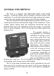
GENERAL DESCRIPTION The LC-8 is a compact and lightweight liquid crystal depth sounder. It indicates depth, shows changes in bottom content, and conditions. It can also discriminate between large underwater targets, such as fish, and smaller targets such as bait fish and plankton. The unit transmits bursts of high frequency pulses, which are converted from electrical to mechanical energy by the transducer.
SPECIFICATIONS * Operating Voltage * Current Draw: * Power Output: * Frequency: * Resolution: * Sounding Rate: * Display Size: * Dimensions: * Weight: 8.5 - 15 Volts (12 Volts Nominal) 50mA or 100 mA with Backlight On 400 Watts (Peak to Peak) 200 Khz 64 x 64 Pixels 400/Min. 2" x 2 1/4" 5.9"H x 6.4"W x 2.5"D 0.6 Lb. Depth Ranges: 0-5', 0-10', 0-15', 0-20', 0-30', 0-40', 0-60', 0-80', 0-120', 0-160', 0-240', 0-320', and 0-400'. (Meter units are selectable from the menu.
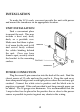
INSTALLATION To make the LC-8 work, you must provide the unit with power and mount the transducer in an appropriate location. UNIT INSTALLATION Find a convenient place to mount the unit. This may include a boat seat, deck, dash, or a portable case. Make sure that there is plenty of room for the unit to tilt and swivel freely without the cables binding behind the unit. Once you have found a spot, securely attach the bracket to the mounting surface.
TRANSDUCER INSTALLATION Transom Mounted The LC-8 transducer can be mounted on the transom of the boat. The shape will allow a clear depth reading at any boat speed. Locate a spot similar to the one in figure E. Keep in mind that you need clear water flow across the face of the transducer to insure a clear reading at all speeds. Stay away from rivets, ribs, or strakes that would be just in front of the transducer. They will disturb the water and scramble the reading.
In-Hull Mounting This method, gluing the transducer to the hull, gets the same results as if you were mounting the transducer externally, only there are no holes to drill in the boat and there is no transducer on the transom to get damaged by impact. Finding the best location for the transducer before mounting is critical. Choose a flat smooth spot near the center of the bilge and near the back of the boat.
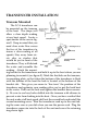
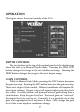
OPERATION This figure shows the main controls of the LC-8 DEPTH CONTROL The two buttons at the top of the control panel set the depth range when the unit is in Manual Depth Mode. Pressing the SHALLOW button changes the range to the next shallowest range. Pressing the DEEP button changes the range to the next deeper range. GAIN CONTROL While in Manual Gain Mode, pressing the DEC button decreases the gain one step. Pressing the INC button increases the gain one step. There are 8 steps of Gain control.
ZOOM ZOOM displays only the bottom half of the water depth. This doubles the display resolution making it much easier to see targets near or on the bottom. Pressing the ZOOM button once puts the LC8 in ZOOM mode. Pressing it again will go back to the normal view. SWEEP SWEEP controls how fast the information moves across the display. There are 4 steps of sweep speed. The sweep speed should roughly match the boat speed to get the most accurate reading.
you read the blue numbers. For instance the SHALLOW button is the 1 key and the DEC button is the 2 key in Menu Mode. MENU PAGE 1 1 - AUTO - R Press the 1 key to enter the Automatic Range Submenu. In this submenu, pressing the 2 key puts the LC-8 into Automatic Range Mode. In this mode the unit changes the range setting for you when the depth of the water changes. Pressing the 2 key puts the unit into the Manual Range Mode.
4 key. As you press the key the displayed setting will change. Press the key until it is set to where you want it. The minimum is 3 feet. Press the 5 key to increase the setting. There is no maximum limit. Press the 1 key to turn the Bottom Alarm off. The default is OFF. 5 - FISH-ALM Press the 5 key to enter the Fish Alarm Submenu. Press the 2 or 3 key to turn the Fish Alarm on. When the 2 selection is chosen the alarm will sound on all fish targets that the LC-8 sees.
set the feature to the setting. Press the 1 key to turn the feature off. 3 - A-MODE Press the 3 key to enter the A-Mode Submenu. A-Mode gives you a vertical representation of the depth. Everything displayed is happening right now. Press the 2 key to select the normal A-Mode setting. This is a "split screen" display. The vertical display will be at the right side and the left side will continue to show the normal graphical representation of the bottom. Press the 3 key to activate the Wide setting.
allows you to test all of the control panel and menu functions without having to be on the water. It displays a short program of what you may see when you are actually out on the water. Press the 2 key to activate the simulator and the 1 key to deactivate it. 2 - OFFSET Press the 2 key to enter the Keel Offset Submenu. The feature allows you to compensate for the depth that the transducer is under the surface of the water.
Unlike open water use, the direction in which the transducer is pointed is very critical. You want your bait to be located in the dead center of the cone sound, directly under the transducer. This way you can see very small baits at low gain settings and also see fish come in from all sides. If you are not using the Ice-Ducer system, the transducer must be attached to an adjustable arm so that it can be manually pointed directly at the bait.
MAINTENANCE PERMANENT MOUNT With permanent mount applications, the power cord is left connected to the source, the transducer is not easily removed, and the gimbal bracket is screwed to the seat, deck, or dash. Under these conditions maintenance is very simple because nothing changes once the unit is installed. Because of this, though, problems can sneak up on you if you're not careful. Power connections need constant checking. Corrosion can develop and cause intermittent or loss of operation.
Trouble Shooting Chart 15
Service and Support If you find that you need help, feel free to contact us. Please have ready the model number and, if possible, the serial number of your product. Be sure to read the Trouble Shooting sections first. Address Vexilar, Inc. 200 W. 88th St. Minneapolis, MN, 55420-2752 Telephone (952) 884-5291 (8 am to 5 PM M-F Central Time) Fax (952) 884-5292 Email service@vexilar.com Web Site www.vexilar.