
Specifications
9
The first step is to detect occlusions. It is assumed that each object that enters the scene also exits
the scene. If this assumption holds, any object track that either ends or begins within the object
frame rather than at the edges of the frame can be assumed to have been occluded. Thus, the
position of the first and last object of each object track is examined. If the first object of the track
is near the image edge, the track is classified as having entered the scene. Otherwise, the track is
classified as having been occluded. If the last object of the track is near the image edge, the track
is classified as having left the scene. Otherwise, the track is classified as having been occluded
before leaving the scene.
Once the occluded object tracks have been identified, the ends of the object tracks are examined
for potential matches across occlusions. Due to the occlusion, spatial position is not a reliable
indicator of object identity. Therefore, the visual features of the object are used as a matching
measure. For each end of the object track that is occluded, a comparison is made between the
visual features of the object and the visual features of objects within λ frames.
The SIFT algorithm (Lowe 1999) is employed to match visual features from object to object.
This matching algorithm provides robust matching performance when the compared objects
differ in position, rotation, scaling, and global changes in color and intensity. Although matching
the visual features of objects is quite slow, it is more reliable than using position alone. Once
links between object tracks have been established, the object tracks are reorganized to create a
master object track list where each track uniquely describes a single scene object.
4.5 Noise Filtering
In order to minimize the effects of noise, temporal averaging is applied to the object tracks. A
noncausal boxcar filter of size τ is run across the object center and bounding box coordinates
separately. The filter size τ should be chosen based on the properties of the camera. It should be
noted that a large filter can result in an underestimation of minimum and maximum velocities.
5. DEPLOYMENT OF DIGITAL VIDEO ANALYSIS SYSTEM AT NON-SIGNALIZED
INTERSECTIONS
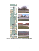
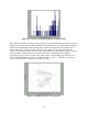
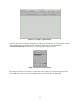
To obtain video that could be used to test the video analysis algorithms, the system was deployed
to a total of five intersections in Ames, Iowa. Four non-signalized intersections on Bissell Road
were chosen. The location of these intersections is shown on the map in Figure 5.1. The position
and direction of the camera in the standard camera–intersection configuration is shown with a
blue box and arrow. A video frame taken from each intersection is also shown.
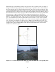
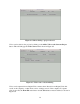
A single, high-speed rural intersection at U.S. 69 and 190th
was also chosen. A collision diagram
and video frame from the recording are shown in Figure 5.2.