
User's Manual


VIA
IVT01 System
User
Manual
5
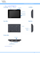
2. Coastline I/O Connectors
This chapter provides information about the coastline connectors of the VIA IVT01 system.
Figure 02: IVT01 connector
2.1 Power Connector
The VIA IVT01 system is equipped with a power connector labeled ‘POWER’. The pinouts of power connector
are shown below.
Pin
Signal Pin
Signal
1 GPI2 2
GPI1
3 GPI4 4
GPI5
5 CAN_L 6
GPI3
7 CAN_H 8
TRIGGER_D
9 VCC_BAT 10
GND
11
VCC_BAT 12
GND
13
VCC_BAT 14
GND
15
ACC_IN 16
IGN_IN
Table 01: POWER connector pinouts