User Guide Motherboard K8V SE Deluxe
E1872 Checklist Revised Edition V2 January 2005 Copyright © 2005 ASUSTeK COMPUTER INC. All Rights Reserved. No part of this manual, including the products and software described in it, may be reproduced, transmitted, transcribed, stored in a retrieval system, or translated into any language in any form or by any means, except documentation kept by the purchaser for backup purposes, without the express written permission of ASUSTeK COMPUTER INC. (“ASUS”).
Contents Features Notices .......................................................................................... vii Safety information ........................................................................ viii About this guide .............................................................................. ix How this guide is organized .................................................. ix Where to find more information ............................................. ix Conventions used in this guide .
Contents Safeguards 2.6 2.7 2.5.3 Interrupt assignments .......................................... 2-16 2.5.4 PCI slots .............................................................. 2-17 2.5.5 AGP slot ............................................................... 2-17 2.5.6 Wi-Fi slot .............................................................. 2-18 Jumpers ............................................................................ 2-19 Connectors ....................................................
Contents 4.4 4.5 4.6 4.7 4.3.2 System Date ........................................................ 4-12 4.3.3 Legacy Diskette A ................................................ 4-12 4.3.4 Language ............................................................. 4-12 4.3.5 Primary and Secondary IDE Master/Slave .......... 4-13 4.3.6 System Information .............................................. 4-14 Advanced menu ............................................................... 4-15 4.4.
Contents 5.6 5.7 5.8 5.9 vi Promise® RAID configurations .......................................... 5-17 5.6.1 Install the hard disks ............................................ 5-18 5.6.2 Enter the MBFastBuild™ utility ............................ 5-19 5.6.3 Creating a RAID 0 array (Performance) .............. 5-20 5.6.4 Creating a RAID 1 array (Security) ...................... 5-21 5.6.5 Other FastBuild Utility Commands ....................... 5-23 VIA RAID configurations ............................
Notices Federal Communications Commission Statement This device complies with Part 15 of the FCC Rules. Operation is subject to the following two conditions: • This device may not cause harmful interference, and • This device must accept any interference received including interference that may cause undesired operation. This equipment has been tested and found to comply with the limits for a Class B digital device, pursuant to Part 15 of the FCC Rules.
Safety information Electrical safety • To prevent electrical shock hazard, disconnect the power cable from the electrical outlet before relocating the system. • When adding or removing devices to or from the system, ensure that the power cables for the devices are unplugged before the signal cables are connected. If possible, disconnect all power cables from the existing system before you add a device.
About this guide This user guide contains the information you need when installing the motherboard. How this guide is organized This manual contains the following parts: • Chapter 1: Product introduction This chapter describes the motherboard features and the new technologies it supports. • Chapter 2: Hardware information This chapter lists the hardware setup procedures that you have to perform when installing system components. It includes description of the jumpers and connectors on the motherboard.
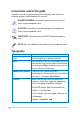
Conventions used in this guide To make sure that you perform certain tasks properly, take note of the following symbols used throughout this manual. DANGER/WARNING: Information to prevent injury to yourself when trying to complete a task. CAUTION: Information to prevent damage to the components when trying to complete a task. IMPORTANT: Information that you MUST follow to complete a task. NOTE: Tips and additional information to aid in completing a task.
K8V SE Deluxe specifications summary CPU Socket 754 for AMD Athlon™ 64 processor with built-in 1MB L2 cache Supports AMD 64 architecture that enables simultaneous 32-bit and 64-bit computing Chipset VIA K8T800 VIA VT8237 System Bus 800 MHz Memory 3 x 184-pin DDR DIMM sockets for up to 3GB unbuffered ECC and non-ECC PC3200/PC2700/PC2100/PC1600 SDRAM memory Expansion slots 1 x AGP 8X/4X 5 x PCI 1 x WiFi slot Storage South Bridge supports - 2 x Ultra ATA 133 connectors - 2 x Serial ATA with RAID 0,
K8V SE Deluxe specifications summary Back panel I/O 1 x Parallel port 1 x Serial port 1 x PS/2 keyboard port 1 x PS/2 mouse port 4 x USB 2.0 ports 1 x IEEE 1394 port 1 x S/PDIF out 1 x RJ-45 port Line In/Line Out/Microphone ports Internal I/O 2 x USB 2.
Chapter 1 This chapter describes the motherboard features and the new technologies it supports.
Chapter summary 1.1 Welcome! ........................................................ 1-1 1.2 Package contents .......................................... 1-1 1.3 Special features .............................................
1.1 Welcome! Thank you for buying the ASUS® K8V SE Deluxe motherboard! The motherboard delivers a host of new features and latest technologies making it another standout in the long line of ASUS quality motherboards! The motherboard combines the powers of the AMD Athlon™ 64 processor and the VIA K8T800 chipset to set a new benchmark for an effective desktop platform solution.
1.3 Special features 1.3.1 Product Highlights Latest processor technology The AMD Athlon™ 64 desktop processor is based on AMD’s 64-bit architecture, which represents the landmark introduction of the industry’s first x86-64 technology. This processor provides a dramatic leap forward in compatibility, performance, investment protection, and reduced total cost of ownership and development.
AGP 8X support AGP 8X (AGP 3.0) is the VGA interface specification that enables enhanced graphics performance with maximum bandwidth speed of up to 2.12 GB/s. S/PDIF out The motherboard’s S/PDIF out function turns your computer into a high-end entertainment system with digital connectivity to powerful speaker systems. IEEE 1394 support The IEEE 1394 interface provides high-speed and flexible PC connectivity to a wide range of peripherals and devices compliant to IEEE 1394a standards.
1.3.2 Unique ASUS features ASUS Wi-Fi slot The ASUS Wi-Fi slot is designed for the ASUS WiFi-b™ add-on card to set up an environment for wireless LAN. The ASUS WiFi-b™ add-on card bundles the exclusive software Access Point (AP) to save the extra cost of a stand-alone AP. In addition, the card comes with user-friendly utilities and applications that allow quick connection to notebooks, PDAs and other wireless LAN peripherals. See page 2-18.
ASUS POST Reporter™ The motherboard offers an exciting feature called the ASUS POST Reporter™ to provide friendly voice messages and alerts during the Power-On Self-Tests (POST). Through an added external speaker, you will hear the messages informing you of the system boot status and causes of boot errors, if any. The bundled Winbond Voice Editor software allows you to customize the voice messages, and provides multi-language support. See page 3-3.
1-6 Chapter 1: Product introduction
Chapter 2 This chapter lists the hardware setup procedures that you have to perform when installing system components. It includes description of the jumpers and connectors on the motherboard.
Chapter summary 2.1 Before you proceed ....................................... 2-1 2.2 Motherboard overview ................................... 2-2 2.3 Central Processing Unit (CPU) ..................... 2-6 2.4 System memory ............................................ 2-11 2.5 Expansion slots ........................................... 2-15 2.6 Jumpers ........................................................ 2-19 2.7 Connectors ...................................................
2.1 Before you proceed Note of the following precautions before you install motherboard components or change any motherboard settings. • Unplug the power cord from the wall socket before touching any component. • Use a grounded wrist strap or touch a safely grounded object or to a metal object, such as the power supply case, before handling components to avoid damaging them due to static electricity. • Hold components by the edges to avoid touching the ICs on them.
2.2 Motherboard overview Before you install the motherboard, study the configuration of your chassis to ensure that the motherboard fits into it. Unplug the power cord before installing or removing the motherboard. Failure to do so may cause you physical injury and damage motherboard components. 2.2.1 Placement direction When installing the motherboard, make sure that you place it into the chassis in the correct orientation.
2.2.3 Motherboard layout 24.5cm (9.6in) PS/2KBMS T: Mouse B: Keyboard CPU_FAN ATX12V PWR_FAN USB2.
2.2.4 Layout Contents 2-4 Slots Page 1. DDR DIMM slots 2-11 2. PCI slots 2-17 3. AGP slot 2-17 4. Wi-Fi slot 2-18 Jumpers Page 1. Clear RTC RAM (3-pin CLRTC) 2-19 2. Keyboard power (3-pin KBPWR) 2-20 3. USB device wake-up (3-pin USBPWR12, USBPWR34, USBPWR56, USBPWR78) 2-20 Rear Panel Connectors Page 1. PS/2 mouse port 2-21 2. Parallel port 2-21 3. IEEE 1394 port 2-21 4. Gigabit LAN port (RJ-45) 2-21 5. Line In jack 2-21 6. Line Out jack 2-21 7. Microphone jack 2-21 8.
Internal Connectors Page 1. Primary IDE connector (40-1 pin PRI_IDE) 2-22 2. Secondary IDE connector (40-1 pin SEC_IDE) 2-22 3. Floppy disk connector (34-1 pin FLOPPY) 2-23 4. RAID ATA connector (40-1 pin PRI_RAID) 2-23 5. Serial ATA connectors (7-pin SATA1, SATA2) 2-24 6. RAID Serial ATA connectors (7-pin SEC_SATA, PRI_SATA) 2-25 7. CPU fan connector (3-pin CPU_FAN) 2-26 8. Power fan connector (3-pin PWR_FAN) 2-26 9. Chassis fan connector (3-pin CHA_FAN) 2-26 10.
2.3 Central Processing Unit (CPU) 2.3.1 Overview The motherboard comes with a surface mount 754-pin Zero Insertion Force (ZIF) socket designed for the AMD Athlon™ 64 processor. The 128-bit-wide data paths of these processors can run applications faster than processors with only 32-bit or 64-bit wide data paths. Take note of the marked corner (with gold triangle) on the CPU. This mark should match a specific corner on the socket to ensure correct installation. Gold triangle 2.3.
2. Unlock the socket by pressing the lever sideways, then lift it up to a 90°-100° angle. Socket Lever Make sure that the socket lever is lifted up to 90°-100° angle, otherwise the CPU does not fit in completely. 3. Position the CPU above the socket such that the CPU corner with the gold triangle matches the socket corner with a small triangle. 4. Carefully insert the CPU into the socket until it fits in place. Gold triangle Small triangle The CPU fits only in one correct orientation.
2.3.3 Installing the heatsink and fan The AMD Athlon™ 64 processor require a specially designed heatsink and fan assembly to ensure optimum thermal condition and performance. Make sure that you use only qualified heatsink and fan assembly. Follow these steps to install the CPU heatsink and fan. 1. Place the heatsink on top of the installed CPU, making sure that the heatsink fits properly on the retention module base. • • The retention module base is already installed on the motherboard upon purchase.
2. Attach one end of the retention bracket to the retention module base. 3. Align the other end of the retention bracket (near the retention bracket lock) to the retention module base. A clicking sound denotes that the retention bracket is in place. Make sure that the fan and heatsink assembly perfectly fits the retention mechanism module base, otherwise you cannot snap the retention bracket in place. 4.
2.3.4 Connecting the CPU fan cable When the heatsink and fan assembly is in place, connect the CPU fan cable to the connector on the motherboard labeled CPU_FAN. CPU Fan Connector (CPU_FAN) Do not forget to connect the CPU fan connector! CPU overheating and hardware monitoring errors may occur if you fail to plug this connector. 2.3.5 CPU heatsink and fan Qualified Vendors List The following table lists the CPU heatsink and fan assembly that have been tested and qualified for use with this motherboard.
2.4 System memory 2.4.1 Overview The motherboard comes with four Double Data Rate (DDR) Dual Inline Memory Module (DIMM) sockets. DIMM3 DIMM2 104 Pins DIMM1 The following figure illustrates the location of the sockets. 80 Pins K8V ® K8V SE Deluxe 184-Pin DDR DIMM Sockets 2.4.2 Memory configurations You may install 64MB, 128MB, 256MB, 512MB, and 1GB unbuffered ECC and non-ECC DDR DIMMs into the DIMM sockets using the memory configurations in this section.
Table 1 Recommended memory configurations Number of DIMMs 1 2-12 DIMM1 Single Side DIMM Slot DIMM2 DIMM3 Max Speed - - DDR 400 1 - Single Side - DDR 400 1 - - Single Side DDR 400 1 Double Side - - DDR 400 1 - Double Side - DDR 400 1 - - Double Side DDR 400 2 Single Side Single Side - DDR 400 2 Single Side Double Side - DDR 400 2 Single Side - Single Side DDR 400 2 Single Side - Double Side DDR 400 2 Double Side Single Side - DDR 400 2 Double Side
DDR Qualified Vendors List The following table lists the PC3200 (DDR400) memory modules that have been tested and qualified for use with this motherboard.
2.4.3 Installing a DIMM Make sure to unplug the power supply before adding or removing DIMMs or other system components. Failure to do so may cause severe damage to both the motherboard and the components. 1. Unlock a DIMM socket by pressing the retaining clips outward. 2. Align a DIMM on the socket such that the notch on the DIMM matches the break on the socket. DDR DIMM NOTCH Unlocked Retaining Clip A DDR DIMM is keyed with a notch so that it fits in only one direction.
2.5 Expansion slots In the future, you may need to install expansion cards. The motherboard has available PCI slots, an Accelerated Graphics Port (AGP) slot and a Wireless Fidelity (Wi-Fi) slot. The following sub-sections describe the slots and the expansion cards that they support. Make sure to unplug the power cord before adding or removing expansion cards. Failure to do so may cause you physical injury and damage motherboard components. 2.5.
2.5.
2.5.4 PCI slots The PCI slots support PCI cards such as a LAN card, SCSI card, USB card, and other cards that comply with PCI specifications. The following figure shows a LAN card installed on a PCI slot. 2.5.5 AGP slot The Accelerated Graphics Port (AGP) slot supports AGP8X/4X cards. When you buy an AGP card, make sure that you ask for one with +1.5V specification. Note the notches on the card golden fingers to ensure that they fit the AGP slot on your motherboard. Install only 1.
2.5.6 Wi-Fi slot The Wi-Fi (Wireless Fidelity) slot will support the ASUS Wi-Fi module. Visit the ASUS website (www.asus.com) for product updates. The Wi-Fi slot conforms to the Institute of Electrical and Electronics Engineers (IEEE) 802.11b/g standard for wireless devices operating in the 2.4 GHz frequency band. K8V WIFI ® K8V SE Deluxe WIRELESS Connectors ASUS WiFi-b™ Setup • • 2-18 The PCI 5 slot and the Wi-Fi slot can not be used at the same time. The ASUS Wi-Fi module is purchased separately.
2.6 Jumpers 1. Clear RTC RAM (CLRTC) This jumper allows you to clear the Real Time Clock (RTC) RAM in CMOS. You can clear the CMOS memory of date, time, and system setup parameters by erasing the CMOS RTC RAM data. The RAM data in CMOS, that include system setup information such as system passwords, is powered by the onboard button cell battery. To erase the RTC RAM: 1. Turn OFF the computer and unplug the power cord. 2. Remove the onboard battery. 3. Move the jumper from pins 1-2 (default) to pins 2-3.
2. Keyboard power (3-pin KBPWR) This jumper allows you to enable or disable the keyboard wake-up feature. Set this jumper to pins 2-3 (+5VSB) if you wish to wake up the computer when you press a key on the keyboard. This feature requires an ATX power supply that can supply at least 1A on the +5VSB lead, and a corresponding setting in the BIOS (See section “4.5.5 APM Configuration”). KBPWR 1 2 2 3 +5V +5VSB (Default) K8V ® K8V SE Deluxe Keyboard Power Setting 3.
2.7 Connectors 2.7.1 Rear panel connectors 1 3 2 4 5 6 7 1. 2. 3. 4. 5. 6. 7. 9 11 10 8 12 PS/2 mouse port. This green 6-pin connector is for a PS/2 mouse. Parallel port. This 25-pin port connects a parallel printer, a scanner, or other devices. IEEE 1394 port. This 6-pin IEEE 1394 port provides high-speed connectivity for audio/video devices, storage peripherals, other PC’s and/or portable devices. RJ-45 port. This port allows connection to a Local Area Network (LAN) through a network hub.
8. USB 2.0 ports 3 and 4. These two 4-pin Universal Serial Bus (USB) ports are available for connecting USB 2.0 devices. 9. USB 2.0 ports 1 and 2. These two 4-pin Universal Serial Bus (USB) ports are available for connecting USB 2.0 devices. 10. Serial connector. This 9-pin COM1 port is for serial devices. 11. S/PDIF out jack. This jack connects to external audio output devices. 12. PS/2 keyboard port. This purple connector is for a PS/2 keyboard. 2.7.2 Internal connectors 1.
2. Floppy disk drive connector (34-1 pin FLOPPY) This connector supports the provided floppy drive ribbon cable. After connecting one end to the motherboard, connect the other end to the floppy drive. (Pin 5 is removed to prevent incorrect insertion when using ribbon cables with pin 5 plug). PIN 1 FLOPPY NOTE: Orient the red markings on the floppy ribbon cable to PIN 1. K8V ® K8V SE Deluxe Floppy Disk Drive Connector 3.
4. Serial ATA connectors (7-pin SATA1, SATA2, ) These next generation connectors support the thin Serial ATA cables for primary internal storage devices. The current Serial ATA interface allows up to 150 MB/s data transfer rate, faster than the standard parallel ATA with 133 MB/s (UltraDMA133).
5. RAID Serial ATA connectors (7-pin SEC_SATA, PRI_SATA) These Serial ATA connectors support SATA hard disks that you may configure as a RAID set. Through the onboard Promise® PDC20378 RAID controller, you may create a RAID 0, RAID 1,or RAID 0+1 configuration together with the RAID ATA133 connector. See Chapter 5 for details on RAID configuration.
6. CPU, Power and Chassis Fan Connectors (3-pin CPU_FAN, PWR_FAN, CHA_FAN) The fan connectors support cooling fans of 350mA~740mA (8.88W max.) or a total of 1A~2.22A (26.64W max.) at +12V. Connect the fan cables to the fan connectors on the motherboard, making sure that the black wire of each cable matches the ground pin of the connector. Do not forget to connect the fan cables to the fan connectors. Lack of sufficient air flow within the system may damage the motherboard components.
8. ATX power connectors (20-pin ATXPWR, 4-pin ATX12V) These connectors connect to an ATX 12V power supply. The plugs from the power supply are designed to fit these connectors in only one orientation. Find the proper orientation and push down firmly until the connectors completely fit. In addition to the 20-pin ATX power connector, this motherboard requires that you connect the 4-pin ATX +12V power plug to provide sufficient power to the CPU. • Do not forget to connect the 4-pin ATX +12V power plug.
9. USB headers (10-1 pin USB56, USB78) If the USB ports on the rear panel are inadequate, a USB header is available for additional USB ports. The USB header complies with USB 2.0 specification that supports up to 480 Mbps connection speed. This speed advantage over the conventional 12 Mbps on USB 1.1 allows faster Internet connection, interactive gaming, and simultaneous running of high-speed peripherals.
10. Internal audio connectors (4-pin CD, AUX) These connectors allow you to receive stereo audio input from sound sources such as a CD-ROM, TV tuner, or MPEG card. CD (Black) AUX (White) Left Audio Channel K8V Ground Right Audio Channel ® K8V SE Deluxe Internal Audio Connectors 11. IEEE 1394 connectors (10-1 pin IE1394_1) This connector is for the bundled IEEE 1394 module. Attach the 10-1 pin cable plug to thiss connector. You may also connect a 1394-compliant internal hard disk to this connector.
12. Front panel audio connector (10-1 pin FP_AUDIO) This is an interface for the front panel audio cable that allow convenient connection and control of audio devices. By default, the pins labeled LINE_OUT_R/BLINE_OUT_R and the pins LINE_OUT_L/BLINE_OUT_L are shorted with jumper caps. Remove the caps only when you are connecting the front panel audio cable. FP_AUDIO K8V BLINE_OUT_L BLINE_OUT_R +5VA AGND ® Line out_L NC Line out_R MICPWR MIC2 K8V SE Deluxe Front Panel Audio Connector 13.
14. GAME/MIDI connector (16-1 pin GAME) This connector supports a GAME/MIDI module. If a GAME/MIDI module is available, connect the GAME/MIDI cable to this connector. The GAME/MIDI port on the module connects a joystick or a game pad for playing games, and MIDI devices for playing or editing audio files. +5V J2B1 J2CX MIDI_OUT J2CY J2B2 MIDI_IN K8V ® GAME +5V J1B1 J1CX GND GND J1CY J1B2 +5V K8V SE Deluxe Game Connector 15.
16. System panel connector (20-pin PANEL) This connector accommodates several system front panel functions. +5V Ground Ground Speaker Reset Ground K8V Speaker Connector PWR Ground PLED- IDE_LED+ IDE_LED- PLED+ Power LED Reset SW ® IDE_LED K8V SE Deluxe System Panel Connector ATX Power Switch* * Requires an ATX power supply. • System Power LED Lead (Green 3-1 pin PLED) This 3-1 pin connector connects to the system power LED.
Chapter 3 This chapter describes the power up sequence, the vocal POST messages and ways of shutting down the system.
Chapter summary 3.1 Starting up for the first time .......................... 3-1 3.2 Powering off the computer ........................... 3-2 3.3 ASUS POST Reporter™ .................................
3.1 Starting up for the first time 1. After making all the connections, replace the system case cover. 2. Make sure that all switches are off. 3. Connect the power cord to the power connector at the back of the system chassis. 4. Connect the power cord to a power outlet that is equipped with a surge protector. 5. Turn on the devices in the following order: a. Monitor b. External SCSI devices (starting with the last device on the chain) c.
3.2 Powering off the computer 3.2.1 Using the OS shut down function If you are using Windows® 98SE/ME/2000: 1. Click the Start button then click Shut Down... 2. Make sure that the Shut down option button is selected, then click the OK button to shut down the computer. 3. The power supply should turn off after Windows® shuts down. If you are using Windows® XP: 1. Click the Start button then select Turn Off Computer. 2. Click the Turn Off button to shut down the computer. 3.
3.3 ASUS POST Reporter™ This motherboard includes the Winbond speech controller to support a special feature called the ASUS POST Reporter™. This feature gives you vocal POST messages and alerts to inform you of system events and boot status. In case of a boot failure, you will hear the specific cause of the problem. These POST messages are customizable using the Winbond Voice Editor software that came with your package. You can record your own messages to replace the default messages. 3.3.
POST Message Action No keyboard detected • Check your keyboard if it is properly connected to the purple PS/2 connector on the rear panel. • See section “2.7.1 Rear panel connectors” for the location of the connector. No IDE hard disk detected • Make sure you have connected an IDE hard disk drive to one of the IDE connectors on the motherboard. CPU temperature too high • Check CPU fan if it is working properly.
3.3.2 Winbond Voice Editor The Winbond Voice Editor software allows you to customize the vocal POST messages. Install the software from the utilities menu of the support CD. See section “5.2.3 Utilities menu” for details. To avoid conflicts, do not run the Winbond Voice Editor while running the ASUS PC Probe. Follow these steps to use the Winbond Voice Editor.
Changing the default language 1. Click the Load button. A window showing the available languages appears. 2. Select your desired language then click Open. The event messages for the language you selected appear on the Voice Editor screen. For some languages, not all events have a corresponding message due to file size constraints. 3. Click the Write button to update the EEPROM. 4. Click Yes on the confirmation window that appears.
Customizing your POST messages If your language is not in the selection or if you wish to record your own POST messages to replace the pre-installed wave files, you may easily do so. Follow these steps to customize your POST messages. 1. Launch the Voice Editor and take note of the list of POST events on the leftmost column of the screen. 2. Prepare your message for each event. The total compressed size for all the wave files must not exceed 1Mbit, so make your messages as short as possible. 3.
7. Select a POST event on the Voice Editor screen, then click the Edit button. The Event Sound Editor window appears. 8. Locate and select your wave file for the event then click on the arrow opposite Voice1. The file you selected appears on the space next to it. 9. Click OK to return to the Voice Editor screen. 10. Do steps 7 to 9 for the other events. 11. When done, click Save. A window appears prompting you to save your configuration. 12. Type a file name with a .flh extension, then click Save. 13.
Chapter 4 This chapter tells how to change the system settings through the BIOS Setup menus. Detailed descriptions of the BIOS parameters are also provided.
Chapter summary 4.1 Managing and updating your BIOS .............. 4-1 4.2 BIOS Setup program ...................................... 4-9 4.3 Main menu .................................................... 4-12 4.4 Advanced menu ........................................... 4-15 4.5 Power menu .................................................. 4-29 4.6 Boot menu .................................................... 4-33 4.7 Exit menu ......................................................
4.1 Managing and updating your BIOS The following utilities allow you to manage and update the motherboard Basic Input/Output System (BIOS) setup. 1. ASUS AFUDOS - Updates the BIOS using a bootable floppy disk in DOS mode. 2. ASUS EZ Flash - Updates the BIOS using a floppy disk during POST. 3. ASUS CrashFree BIOS 2 - Updates the BIOS using a bootable floppy disk or the motherboard support CD. 4. ASUS Update - Updates the BIOS in a Windows® environment.
2. Copy the original (or the latest) motherboard BIOS to the bootable floppy disk. 4.1.2 Using AFUDOS to update the BIOS To update the BIOS using the AFUDOS.EXE utility: 1. Visit the ASUS website (www.asus.com) to download the latest BIOS file for your motherboard. Save the BIOS file to a bootable floppy disk. Write the BIOS file name on a piece of paper. You need to type the exact BIOS file name at the prompt. 2. Copy the AFUDOS.
When the BIOS update process is complete, the utility returns to the DOS prompt. A:\>afudos /iK8VSEDX.ROM AMI Firmware Update Utility - Version 1.10 Copyright (C) 2002 American Megatrends, Inc. All rights reserved. Reading file ..... done Erasing flash .... done Writing flash .... 0x0008CC00 (9%) Verifying flash .. done A:\> 5. Reboot the system from the hard disk. 4.1.3 Using AFUDOS to copy BIOS from PC You can use the AFUDOS.
3. The utility will copy the current system BIOS by default to the floppy disk. Make sure that the floppy disk has at least 600KB of free disk space and is not write-protected. A:\>afudos /oMYBIOS03.rom AMI Firmware Update Utility - Version 1.10 Copyright (C) 2002 American Megatrends, Inc. All rights reserved. Reading flash ..... done A:\> When the copy process is complete, the utility returns to the DOS prompt. 4.1.
4. Insert the floppy disk that contains the BIOS file. If all the necessary files are found in the floppy disk, EZ Flash performs the BIOS update process and automatically reboots the system when done. DO NOT shutdown or reset the system while updating the BIOS! Doing so may cause system boot failure! User recovery requested. Starting BIOS recovery... Checking for floppy... Floppy found! Reading file “K8VSEDX.rom”. Completed. Start flashing... Flashed successfully. Rebooting. 4.1.
3. Insert a floppy disk that contains the original or the latest BIOS file for this motherboard. If all the necessary files are found in the floppy disk, the BIOS update process continues. Make sure that the BIOS file in the floppy disk is renamed as “K8VSEDX.ROM”. Bad BIOS checksum. Starting BIOS recovery... Checking for floppy... Floppy found! Reading file “K8VSEDX.ROM”. Completed. Start flashing... DO NOT shutdown or reset the system while updating the BIOS! Doing so may cause system boot failure! 4.
DO NOT shut down or reset the system while updating the BIOS! Doing so may cause system boot failure! 4. When the BIOS update process is complete, reboot the system. The recovered BIOS may not be the latest BIOS version for this motherboard. Visit ASUS website (www.asus.com) to download the latest BIOS file. 4.1.6 ASUS Update The ASUS Update is a utility that allows you to update the motherboard BIOS in Windows® environment.
3. If you select updating/ downloading from the Internet, select the ASUS FTP site nearest you to avoid network traffic, or choose Auto Select. Click Next. 4. From the FTP site, select the BIOS version that you wish to download. Click Next. 5. Follow the instructions on the succeeding screens to complete the update process. 6. If you select the option to update the BIOS from a file, a window prompts you to locate the file.
4.2 BIOS Setup program This motherboard supports a programmable firmware chip that you can update using the provided utility described in section “4.1 Managing and updating your BIOS.” Use the BIOS Setup program when you are installing a motherboard, reconfiguring your system, or prompted to “Run Setup”. This section explains how to configure your system using this utility. Even if you are not prompted to use the Setup program, you may want to change the configuration of your computer in the future.
4.2.1 BIOS menu screen Menu items Menu bar System Time System Date Legacy Diskette A Language Primary IDE Master Primary IDE Slave Secondary IDE Master Secondary IDE Slave Third IDE Master Fourth IDE Master IDE Configuration Configuration fields [11:10:19] [Thu 03/27/2003] [1.44M, 3.5 in] [English] :[ST320413A] :[ASUS CD-S340] :[Not Detected] :[Not Detected] :[Not Detected] :[Not Detected] System Information Sub-menu items General help Use [ENTER], [TAB] or [SHIFT-TAB] to select a field.
4.2.4 Menu items The highlighted item on the menu bar displays the specific items for that menu. For example, selecting Main shows the Main menu items. The other items (Advanced, Power, Boot, and Exit) on the menu bar have their respective menu items. System Time System Date Legacy Diskette A Language Primary IDE Master Primary IDE Slave Secondary IDE Master Secondary IDE Slave Third IDE Master Fourth IDE Master IDE Configuration [11:10:19] [Thu 03/27/2003] [1.44M, 3.
4.3 Main menu When you enter the BIOS Setup program, the Main menu screen appears giving you an overview of the basic system information. Refer to section “4.2.1 BIOS menu screen” for information on the menu screen items and how to navigate through them. System Time System Date Legacy Diskette A Language Primary IDE Master Primary IDE Slave Secondary IDE Master Secondary IDE Slave [11:51:19] [Thu 08/05/2003] [1.44M, 3.5 in] [English] Use [ENTER], [TAB] or [SHIFT-TAB] to select a field.
4.3.5 Primary and Secondary IDE Master/Slave While entering Setup, BIOS auto-detects the presence of IDE devices. There is a separate sub-menu for each IDE device. Select a device item then press to display the IDE device information. Primary IDE Master Device : Hard Disk Vendor : ST320413A Size : 20.
PIO Mode [Auto] Selects the PIO mode. Configuration options: [Auto] [0] [1] [2] [3] [4] DMA Mode [Auto] Selects the DMA mode. Configuration options: [Auto] [SWDMA0] [SWDMA1] [SWDMA2] [MWDMA0] [MWDMA1] [MWDMA2] [UDMA0] [UDMA1] [UDMA2] [UDMA3] [UDMA4] [UDMA5] SMART Monitoring [Auto] Sets the Smart Monitoring, Analysis, and Reporting Technology. Configuration options: [Auto] [Disabled] [Enabled] 32Bit Data Transfer [Disabled] Enables or disables 32-bit data transfer.
4.4 Advanced menu The Advanced menu items allow you to change the settings for the CPU and other system devices. Take caution when changing the settings of the Advanced menu items. Incorrect field values may cause the system to malfunction. CPU Configuration Chipset Onboard Devices Configuration PCI PnP JumperFree Configuration Speech Configuration Instant Music Configuration Configure CPU. 4.4.1 CPU Configuration The items in this menu show the CPU-related information auto-detected by BIOS.
HyperTransport Configuration HyperTransport Configuration HT Tristate Enabled CRC Flood Enable HT Frequency HT DATA Width (Upstream) HT DATA Width (Downstream) [Enabled] [Disabled] [800 MHz] [16 BIT] [16 BIT] Enabled link tristate during the disconnect state of an LDTSTOP HT Tristate Enable [Enabled] Enables or disables the HyperTransport Tristate that enables the tristate link during the disconnected state of an LDTSTOP.
Memory Configuration Memory Configuration Memory Configuration ECC Configuration Memory Configuration The Memory configuration menu item allows you to change the memory settings. Select an item then press to display the sub-menu.
TRC [Auto] Sets the TRC. Configuration options: [Auto] [7 CLK] [8 CLK] [9 CLK] [10 CLK] [11 CLK] [12 CLK] [13 CLK] TRFC [Auto] Sets the TRFC. Configuration options: [Auto] [9 CLK] [10 CLK] [11 CLK] [12 CLK] [13 CLK] [14 CLK] [15 CLK] TRCD [Auto] Sets the TRCD. Configuration options: [Auto] [2 CLK] [3 CLK] [4 CLK] [5 CLK] [6 CLK] TWR [Auto] Sets the TWR. Configuration options: [Auto] [2 CLK] [3 CLK] TRWT [Auto] Sets the TRWT.
ECC Configuration ECC Configuration Master ECC Enable [Disabled] Master ECC Enables support on all nodes for ECC error detect and correction. Master ECC Enable [Disabled] Enables or disables support on all nodes for ECC error detect and correction. Configuration options: [Disabled] [Enabled] The following items appear only when the Master ECC Enable item is set to [Enabled].
The following items appear only when the DRAM ECC Enable item is set to [Enabled]. DRAM BG Scrub [60ns] Disables or sets the DRAM scrubbing functionality that corrects and rewrites memory errors so later reads are correct. Doing this while the memory is not being used improves performance. Configuration options: [Disabled] [40ns] [80ns] [160ns] [320ns] [640ns] [1.28us] [2.56us] [5.12us] [10.2us] [20.5us] [41.0us] [81.9us] [163.8us] [327.7us] [655.4us] [1.31ms] [2.62ms] [5.24ms] [10.49ms] [20.97ms] [42.
4.4.2 Chipset The Chipset menu items allow you to change the advanced chipset settings. Select an item then press to display the sub-menu. AGP Bridge Configuration SouthBridge Configuration USB Configuration Options for VIA AGP Chipset AGP Bridge Configuration Primary Graphics Adapter Search for MDA Resources [AGP] [Yes] AGP Mode AGP Fast Write Graphics Aperture Size [AGP 8X] [Enabled] [64MB] Primary Graphics Adapter [AGP] Switches the PCI Bus scanning order while searching for a video card.
AGP Fast Write [Enabled] Enables or disables the AGP Fast Write feature. Configuration options: [Disabled] [Enabled] Graphics Aperture Size [64MB] Allows you to select the size of mapped memory for AGP graphic data. Configuration options: [32MB] [64MB] [128MB] [256MB] SouthBridge Configuration MPS Revision PCI Delay Transaction [1.4] [Disabled] MPS Revision [1.4] Sets the MPS revision value. Configuration options: [1.1] [1.
USB 1.1 Ports Configuration [USB 8 Ports] Allows you to set the number of USB ports to activate. Configuration options: [Disabled] [USB 2 Ports] [USB 4 Ports] [USB 6 Ports] [USB 8 Ports] USB 2.0 Controller [Enabled] Allows you to enable or disable the USB 2.0 ports controller. Configuration options: [Disabled] [Enabled] Legacy USB Support [Auto] Allows you to enable or disable support for legacy USB devices. Setting to Auto allows the system to detect the presence of USB devices at startup.
OnBoard Promise Controller [Enabled] Allows you to enable or disable the onboard Promise® RAID controller. Configuration options: [Disabled] [Enabled] Operating Mode [RAID] This item sets the onboard Promise controller operating mode. This item appears only when the Onboard Promise Controller item is set to Enabled. Configuration options: [RAID] [Onboard IDE Operate Mode] OnBoard LAN [Enabled] Allows you to enable or disable the onboard LAN controller.
ECP Mode DMA Channel [DMA3] Appears only when the Parallel Port Mode is set to [ECP]. This item allows you to set the Parallel Port ECP DMA. Configuration options: [DMA0] [DMA1] [DMA3] Parallel Port IRQ [IRQ7] Sets the Parallel Port IRQ. Configuration options: [IRQ5] [IRQ7] Onboard Game Port [Disabled] Enables or disables the onboard GAME port. Configuration options: [Disabled] [Enabled] Onboard MIDI Port [Disabled] Enables or disables the onboard MIDI port.
Palette Snooping [Disabled] When set to [Enabled], the pallete snooping feature informs the PCI devices that an ISA graphics device is installed in the system so that the latter can function correctly. Setting to [Disabled] deactivates this feature. Configuration options: [Disabled] [Enabled] IRQ xx [Available] When set to [Available], the specific IRQ is free for use of PCI/PnP devices. When set to [Reserved], the IRQ is reserved for legacy ISA devices. Configuration options: [Available] [Reserved] 4.4.
CPU Voltage [1.400 V] Allows you to manually set the CPU voltage. This item appears only when the CPU Speed/Voltage Setting item is set to Manual. Configuration options: [1.750 V] [1.725 V] [1.700 V] [1.675 V] [1.650 V] [1.625 V] [1.600 V] [1.575 V] [1.550 V] [1.525 V] [1.500 V] [1.475 V] [1.450 V] [1.425 V] [1.400 V] [1.375 V] [1.350 V] [1.325 V] [1.300 V] [1.275 V] [1.250 V] [1.225 V] [1.200 V] [1.175 V] [1.150 V] [1.125 V] [1.100 V] [1.075 V] [1.050 V] [1.025 V] [1.000 V] [0.975 V] [0.950 V] [0.
The following items appear only when Speech POST Reporter™ is set to Enabled. Report IDE Error [Disabled] This item enables or disables the Report IDE Error feature. Configuration options: [Disabled] [Enabled] Report System Checking [Disabled] This item enables or disables the Report System Checking feature. Configuration options: [Disabled] [Enabled] Report System Booting [Disabled] This item enables or disables the Report System Booting feature. Configuration options: [Disabled] [Enabled] 4.4.
4.5 Power menu The Power menu items allow you to change the settings for the Advanced Power Management (APM) feature. Select an item then press to display the configuration options. Suspend Mode Repost Video on S3 Resume ACPI 2.0 Support ACPI APIC Support [S1 (POS) & S3 (STR] [No] [No] [Enabled] Select the ACPI state used for System Suspend. APM Configuration Hardware Monitor 4.5.1 Suspend Mode [S1 (POS) & S3 (STR)] Allows you to select the ACPI state to be used for system suspend.
4.5.
Hard Disk Time Out (Minute) [Disabled] Allows you to select the specified time in minute at which the hard disk goes on standby mode. Configuration options: [Disabled] [1] [2] ~ [15] Video Power Down Mode [Suspend] Allows you to select the video power down mode. Configuration options: [Disabled] [Standby] [Suspend] Hard Disk Power Down Mode [Enabled] Allows you to enable or disable the hard disk power down mode.
Power On PS/2 Mouse [Disabled] When set to [Enabled], this parameter allows you to use the PS/2 mouse to resume the system. This feature requires an ATX power supply that provides at least 1A on the +5VSB lead. Configuration options: [Disabled] [Enabled] 4.5.6 Hardware Monitor Hardware Monitor CPU Temperature CPU Temperature MB Temperature [40.5ºC/104.5ºF] [33ªC/91ºF] CPU Fan Speed Chassis Fan Speed [3260RPM] [N/A] Q-Fan Control [Disabled] VCORE Voltage 3.3V Voltage 5V Voltage 12V Voltage [ 1.
If any of the monitored items is out of range, the following error message appears: “Hardware Monitor found an error. Enter Power setup menu for details”. You will then be prompted to “Press F1 to continue or DEL to enter SETUP”. 4.6 Boot menu The Boot menu items allow you to change the system boot options. Select an item then press to display the sub-menu. Boot Settings Specifies the Boot Device Priority sequence. Boot Device Priority Boot Settings Configuration Security 4.6.
4.6.2 Boot Settings Configuration Boot Settings Configuration Quick Boot Full Screen Logo AddOn ROM Display Mode Bootup Num-Lock PS/2 Mouse Support Wait for ‘F1’ If Error Hit ‘DEL’ Message Display [Enabled] [Enabled] [Force BIOS] [On] [Auto] [Enabled] [Enabled] Interrupt 19 Capture [Disabled] Allows BIOS to skip certain tests while booting. This will decrease the time needed to boot the system.
Hit ‘DEL’ Message Display [Enabled] When set to Enabled, the system displays the message “Press DEL to run Setup” during POST. Configuration options: [Disabled] [Enabled] Interrupt 19 Capture [Disabled] When set to [Enabled], this function allows the option ROMs to trap Interrupt 19. Configuration options: [Disabled] [Enabled] 4.6.3 Security The Security menu items allow you to change the system security settings. Select an item then press to display the configuration options.
To clear the supervisor password, select the Change Supervisor Password then press . The message “Password Uninstalled” appears. If you forget your BIOS password, you can clear clear it by erasing the CMOS Real Time Clock (RTC) RAM. See section “2.6 Jumpers” for information on how to erase the RTC RAM. After you have set a supervisor password, the other items appear to allow you to change other security settings.
3. Confirm the password when prompted. The message “Password Installed” appears after you have successfully set your password. The User Password item now shows Installed. To change the user password, follow the same steps as in setting a user password. Clear User Password Select this item if you wish to clear the user password. Password Check [Setup] When set to [Setup], BIOS checks for user password when accessing the Setup utility.
Exit & Save Changes Once you are finished making your selections, choose this option from the Exit menu to ensure that the values you selected are saved to the CMOS RAM. An onboard backup battery sustains the CMOS RAM and stays on even when the PC is turned off. When you select this option, a confirmation window appears. Select Yes to save changes and exit.
Chapter 5 This chapter describes the contents of the support CD that comes with the motherboard package.
Chapter summary 5.1 Install an operating system ........................... 5-1 5.2 Support CD information ................................ 5-1 5.3 Software Information ..................................... 5-7 5.4 AI Net feature ................................................ 5-12 5.5 Multi-audio feature ....................................... 5-13 5.6 Promise® RAID configurations ................... 5-17 5.7 VIA RAID configurations ............................. 5-25 5.
5.1 Install an operating system This motherboard supports Windows® 98SE/ME/2000/2003 Server/XP operating systems (OS). Always install the latest OS version and corresponding updates to maximize the features of your hardware. Motherboard settings and hardware options vary, so use the setup procedures presented in this chapter for general reference only. Refer to your OS documentation for more information. 5.
5.2.2 Drivers menu The drivers menu shows the available device drivers if the system detects installed devices. Install the necessary drivers to activate the devices. VIA 4 in 1 drivers This item installs the following drivers: - VIA Registry (INF) driver - VIA AGP VxD driver - VIA ATAPI vendor support driver - VIA PCI IRQ Miniport driver. Promise FastTrak 378 Driver Installs the Promise FastTrak 378 driver for Serial ATA and RAID features.
Cool ‘n’ Quiet Driver Installs the AMD Cool ‘n’ Quiet!™ Technology driver. The screen display and drivers option may not be the same for different operating system versions. 5.2.3 Utilities menu The Utilities menu shows the applications and other software that the motherboard supports. ASUS PC Probe This smart utility monitors the fan speed, CPU temperature, and system voltages, and alerts you of any detected problems. This utility helps you keep your computer in healthy operating condition.
Anti-virus Utility The anti-virus application scans, identifies, and removes computer viruses. View the online help for detailed information. Acrobat Reader Installs the Adobe Acrobat® Reader V5.0. The Acrobat Reader software is for viewing files saved in Portable Document Format (PDF). ASUS Screen Saver Installs the ASUS screen saver. Promise Array Management Utility Installs the Promise Array Management Utility. Use this utility to configure a disk array for RAID installations.
5.2.5 Other information The icons on the top right corner of the screen give additional information on the motherboard and the contents of the support CD. Click an icon to display the specified information. Motherboard Info Displays the general specifications of the motherboard. Browse this CD Displays the support CD contents in graphical format.
Technical Support Form Displays the ASUS Technical Support Request Form that you have to fill up when requesting technical support. Filelist Displays the contents of the support CD and a brief description of each in text format.
5.3 Software Information Most of the applications in the support CD have wizards that will conveniently guide you through the installation. View the online help or readme file that came with the software for more information. This section provides details of the software applications that the motherboard supports. 5.3.1 ASUS MyLogo2™ The ASUS MyLogo2™ is automatically installed when you install the ASUS Update utility from the software menu. See section “5.2.3 Utilities menu”.
4. From the selection that appears, choose a logo image. Click Next. You may create your own boot logo image in GIF, JPG, or BMP file formats. 5. When you click on an image, it displays larger on the MyLogo2 screen. To make the logo image smaller, click on the arrow on the Ratio item and select your desired scale. 6. The next screen prompts you to flash the original BIOS to update it with the new boot logo. Click Flash to update the BIOS. 7. When finished, click Exit, then reboot your computer.
5.3.2 ASUS Instant Music The motherboard is equipped with a BIOS-based audio playback feature called Instant Music. The onboard audio AC’97 CODEC supports this feature, which requires an optical drive (CD-ROM, DVD-ROM, or CD-RW). • • • Instant Music only supports CDs in audio format. Instant Music does not work if you installed and enabled an add-on sound card. Instant Music only supports PS/2 keyboard. To enable ASUS Instant Music: 1.
To use ASUS Instant Music: 1. Ensure that the power cord is plugged to a grounded power source, so that the system has standby power. 2. Use either one of the two sets of special function keys on your keyboard to play audio CDs. These keys only function as indicated if you enabled the Instant Music item in BIOS. Instant Music function keys (Set 1) CD ON/OFF PLAY/PAUSE Esc F1 STOP/EJECT PREVIOUS NEXT F3 F4 F2 VOL. DOWN VOL.
6. Press or the to play the first track on the CD. If there is no CD in the drive and you press or , the drive tray ejects. 7. Refer to the Instant Music function key definitions on the previous page to select other tracks or control the volume. 8. Press or once to stop playing the CD. Press or one more time to eject the CD.
5.4 AI Net feature The motherboard supports the Marvell® Virtual Cable Tester (VCT) Technology. The VCT virtually diagnoses and reports cable faults using the Time Domain Reflectometry (TDR). The VCT technology detects and reports open and shorted cables with up to one meter of accuracy. It also detects impedance mismatches, pair swaps, pair polarity problems, and pair skew problems of up to 64ns.
5.5 Multi-audio feature The ADI AD1980 SoundMAX® AC ‘97 audio CODEC provides 6-channel audio capability. Install the SoundMAX Audio Driver and Application from the support CD that came with the motherboard package to activate the 6-channel audio feature. Use 4-channel or 6-channel speakers for this setup. Setting to multi-channel audio After installing the audio driver, you can adjust the audio settings to avail the 6-channel audio feature onboard. 1.
8. After selecting an option, test your setting by clicking the Play Test Noise button. While testing, you will see a black circle moving on the screen indicating the audio path. The Play Test Noise button becomes Stop Playing button. Click this button any time to stop playing. Audio path indicator 9. Click the Close button when done. 10. The MIDI Music Synthesizer screen allows you to select a setting for the MIDI. 11. Click the arrow under Synthesizer Default Set to display a list of options.
Adjusting the volume settings 1. After rebooting the system, click the Volume Control icon on the taskbar (lower right corner of your desktop) to display the Volume Control panel. Volume Control icon Proceed to step 3 if you did not install an S/PDIF module. 2. If you installed an S/PDIF module, click on the Volume Control Advanced button from the Volume Control panel. The Advanced Controls for Volume Control window appears.
Adjusting the microphone settings 1. Click on the Microphone Advanced button to display the Advanced Controls for Microphone window. 2. Check the box opposite Mic2 Select to enable the front panel microphone, if you installed a front panel audio device such as the ASUS iPanel. 3. Click Close to effect the new setting. The rear panel microphone is automatically disabled when you enable the front panel microphone. Only one microphone port works at a time.
5.6 Promise® RAID configurations The motherboard includes the Promise® PDC20378 controller chipset to support Redundant Array of Independent Disks (RAID) configurations. Using two Serial ATA hard disks on SATA_RAID1/SATA_RAID2 interfaces, and two UltraDMA133 hard disks on the PRI_RAID interface, you may set up RAID 0, RAID 1, RAID 0+1, and Multi-RAID configurations. Use the MBFastTrak378™ BIOS and the FastBuild™ utility to configure a disk array.
5.6.1 Installing the hard disks The PDC20378 chipset supports UltraDMA 133/100/66 hard disk drives. For optimal performance, install identical drives of the same model and capacity when creating a disk array. • If you are creating a RAID 0 (striping) array for perfomance, use two new drives. • If you are creating a RAID 1 (mirroring) array for protection, you can use two new drives or use an existing drive and a new drive (the new drive must be of the same size or larger than the existing drive).
5.6.2 Entering the MBFastBuild™ utility 1. Boot the system. If this is the first time you boot the system with the new hard disks installed and connected to the ATAIDE connectors on the motherboard, the MBFastTrak378™ BIOS displays the following: MBFastTrak378 (tm) BIOS version 1.00 (c)2000-2005 Promise Technology, Inc. All Rights Reserved. No Array defined... Press to enter FastBuild (tm) Utility Or press key to continue booting. 2.
5.6.3 Creating a RAID 0 array (Performance) 1. In the FastBuild™ utility main menu, press <1> to select Auto Setup. The following screen appears. FastBuild (tm) Utility 2.00 (c) 2002-2005 Promise Technology, Inc. [ Auto Setup Options Menu ] Optimize Array for: Performance [ Array Setup Configuration ] Mode ........................................ Stripe Spare Drive.................................. 0 Drive(s) Used in Array....................... 2 Array Disk Capacity (size in MB).............
5.6.4 Creating a RAID 1 array (Security) Creating a Security Array with New Drives 1. In the FastBuild™ utility main menu, press <1> to select Auto Setup. FastBuild (tm) Utility 2.00 (c) 2002-2005 Promise Technology, Inc. [ Auto Setup Options Menu ] Optimize Array for: Security [ Array Setup Configuration ] Mode ........................................ Mirror Spare Drive.................................. 0 Drive(s) Used in Array....................... 2 Array Disk Capacity (size in MB).............
7. Use the FDISK utility and follow the format procedure for installing a new hard drive. After you have formatted the arrayed drives, install an operating system (OS). During the OS installation, the system prompts you to install third-party SCSI or RAID driver. Refer to section “5.8 Creating a RAID driver disk” for details.
8. Press to continue. Press to return to the main menu. 9. When complete, the utility prompts that your Security array has been created. 10. Press any key to reboot the system. 11. Install an operating system. During the OS installation, the system prompts you to install third-party SCSI or RAID driver. Refer to section “5.8 Creating a floppy with RAID driver” for details. 5.6.
FastBuild (tm) Utility 2.00 (c) 2002-2005 Promise Technology, Inc. [ Rebuild Array Menu ] Array No RAID Mode Array Array Array Array Mirror/Stripe ------------- 1 2 3 4 Total Drv Capacity 4 ------------- Status 7999 ------------- Critical ------------- [ Keys Available ] [ ] Up [ ] Down [ESC] Exit [Enter] Select 7. Select the replacement drive then press . FastBuild (tm) Utility 2.00 (c) 2002-2005 Promise Technology, Inc.
5.7 VIA RAID configurations The motherboard includes a high performance IDE RAID controller integrated in the VIA VT8237 southbridge chipset. It supports RAID 0 and RAID 1 with two independent Serial ATA channels. RAID 0 (called data striping) optimizes two identical hard disk drives to read and write data in parallel, interleaved stacks. Two hard disks perform the same work as a single drive but at a sustained data transfer rate, double that of a single disk alone, thus improving data access and storage.
5.7.1 Installing the Serial ATA (SATA) hard disks The VIA VT8237 southbridge chipset supports Serial ATA hard disk drives. For optimal performance, install identical drives of the same model and capacity when creating a RAID set. If you are creating a RAID 0 (striping) array for perfomance, use two new drives.
5.7.2 Entering VIA Tech RAID BIOS Utility 1. Boot-up your computer. 2. During POST, press to enter VIA RAID configuration utility. The following menu options will appear. The RAID BIOS information on the setup screen shown below is for reference only. What you see on your screen may not exactly match what is shown here. VIA Tech. RAID BIOS Ver 1.
5.7.3 Create Array 1. In the VIA RAID BIOS utility main menu, select Create Array then press . The main menu items on the upper-left corner of the screen are replaced with create array menu options. VIA Tech. RAID BIOS Ver 1.
TIP: For server systems, use of a lower array block size is recommended. For multimedia computer systems used mainly for audio and video editing, a higher array block size is recommended for optimum performance. 4K 8K 16K 32K 64K Use arrow keys to move selection bar on items and press to select. 5. Select Start Create Process and press to set up hard disk for RAID system. The following confirmation message appears: The data on the selected disks will be destroyed.
4. Select Select Disk Drives, then press . Use arrow keys to select disk drive/s, then press to mark selected drive. (An asterisk is placed before a selected drive.) 5. Select Start Create Process and press to setup hard disk for RAID system. The following confirmation message appears: The data on the selected disks will be destroyed. Continue? Press Y/N The same confirmation message appears when you select the Auto Setup for Data Security option. 6.
5.7.5 Select Boot Array 1. In the VIA RAID BIOS utility main menu, select Select Boot Array then press . The focus is directed to the list of channel used for IDE RAID arrays. 2. Press to select a RAID array for boot. The Status of the selected array will change to Boot. Press to return to menu items. Follow the same procedure to deselect the the boot array. ESC : Exit Channel Drive Name Array Name Mode Size(GB) Status Serial_Ch0 Master XXXXXXXXXX xxxxx xxx.
5.8 Creating a RAID driver disk A floppy disk with the Promise® SATA 378 or FastTrak 378 driver is required when installing Windows® XP/2000 operating system. You can create a RAID driver disk using Makedisk.exe utility. To create a RAID driver disk: 1. Insert the motherboard support CD into the CD-ROM drive and locate the Makedisk.exe utility for your RAID controller. A. The Makedisk.exe utility for the FastTrak 378 driver is located in “\Drivers\Promise\378RAID\Makedisk.
5.9 Cool ‘n’ Quiet!™ Technology The motherboard supports the AMD Cool ‘n’ Quiet!™ Technology that dynamically and automatically change the CPU speed, voltage and amount of power depending on the task the CPU performs. To enable Cool ‘n’ Quiet!™ Technology: 1. Turn on the system and enter BIOS by pressing the key during the Power On Self-Tests (POST). 2. In the Advanced -> CPU Configuration -> AMD CPU Cool & Quiet Configuration menu, select the item Cool N’Quiet and set it to Enabled. See section “4.
If you are using Windows® 98SE/ME operating system: 1. From the Windows® 98SE/ME operating system, click the Start button. Select Settings, then Control Panel. 2. Double-click the Display icon in the Control Panel then select the Screen Saver tab. 3. From the Energy saving features of monitor group, click the Settings... button. 4. From the Power Options Properties dialog box, select the AMD’s Cool ‘n’ Quiet(tm) Technology tab. 5. Click the Performance combo list box to select desired mode.