VCN700-LIC10/15 VIA CN700 Mini-ITX Motherboard User’s Manual Ver. 1.
VCN700-LIC10/15 Contents Safety Information ..........................................................................................................4 Technical Support ............................................................................................................5 Conventions Used in This Guide ....................................................................................5 Packing List .....................................................................................................
User’s Manual Contents 1.7.10 Amplifier Connector (JAMP1) .................................................................................................... 25 1.7.11 LCD Inverter Connector (JBKL1) ............................................................................................... 26 1.7.12 LVDS Connector (JLVDS1) ....................................................................................................... 27 1.7.13 SPI Pin Header Connector (JSPI) ............................
VCN700-LIC10/15 Safety Information Electrical safety To prevent electrical shock hazard, disconnect the power cable from the electrical outlet before relocating the system. When adding or removing devices to or from the system, ensure that the power cables for the devices are unplugged before the signal cables are connected. If possible, disconnect all power cables from the existing system before you add a device.
User’s Manual Technical Support If a problem arises with your system and no solution can be obtained from the user’s manual, please contact your place of purchase or local distributor. Alternatively, please try the following help resources for further guidance. Visit the Advansus website for FAQ, technical guide, BIOS updates, driver updates, and other information: http://www.advansus.com.tw/Support/Support.
VCN700-LIC10/15 Revision History Revision V 1.00 6 Revision History First release for PCB 1.
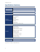
User’s Manual Specifications Summary CPU Features On board VIA C7 1.0/1.5 GHz Chipset VIA CN700 Memory One 240-pin DIMM up to total 1GB DDR2 400/533 SDRAM Display 1 x VGA, 1 x LVDS 24 bit Audio LAN Expansion I/O Others Realtek® ALC655, 5.1 Channel Audio Dual Realtek RTL 8110SC Gigabit LAN 1 x PCI 2 x IDE, 2 x SATAII, 6 x USB 2.0, 2 x COM 4 bit DIO (4-in or 4-out), 6W Amp System CPU VIA C7 1.0/1.
VCN700-LIC10/15 Specifications Summary Audio Audio Codec Realtek® ALC655, 5.1 Channel Audio Audio Interface Mic in, Line in, Line out Audio Amplifier (W) Dual 6W Amp.(TPA3005D2 ) Ethernet LAN1 Realtek RTL 8110SC Gigabit LAN Back I/O Port 1 x PS2 mouse port 1 x PS2 keyboard port 1 x VGA port Back Panel 1 x LPT port 1 x RS-232 COM port 1 x LAN port 4 x USB 2.
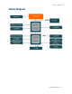
User’s Manual Block Diagram VCN700-LIC10/15 9
VCN700-LIC10/15 This chapter describes the main board features and the new technologies it supports.
User’s Manual Production Introduction 1.1 Before you Proceed Take note of the following precautions before you install motherboard components or change any motherboard settings. Unplug the power cord from the wall socket before touching any component.
VCN700-LIC10/15 1.
User’s Manual 1.4 System Memory 1.4.1 DIMM Sockets Location The motherboard comes with four 240-pin Double Data Rate 2 (DDR2) Dual Inline Memory Modules (DIMM) sockets. A DDR2 module has the same physical dimensions as a DDR DIMM but has a 240-pin footprint compared to the 184-pin DDR DIMM. DDR2 DIMMs are notched differently to prevent installation on a DDR DIMM socket.
VCN700-LIC10/15 1.4.2 Installing a DDR2 DIMM Make sure to unplug the power supply before adding or removing DIMMs or other system components. Failure to do so may cause severe damage to both the motherboard and the components. 1. Unlock a DIMM socket by pressing the retaining clips outward 2. 3. Align a DIMM on the socket such that the notch on the DIMM matches the break on the socket. Firmly insert the DIMM into the socket until the retaining clips snap back in place and the DIMM.
User’s Manual 1.5 Expansion Slots In the future, you may need to install expansion cards. The following sub‑sections describe the slots and the expansion cards that they support. Make sure to unplug the power cord before adding or removing expansion cards. Failure to do so may cause you physical injury and damage motherboard components. 1.5.1 Installing an Expansion Card 1. Before installing the expansion card, read the documentation that came with it and make the necessary hardware settings for the card.
VCN700-LIC10/15 1.6 Jumpers 1.6.1 Clear CMOS (CLRTC) This jumper allows you to clear the Real Time Clock (RTC) RAM in CMOS. You can clear the CMOS memory of date, time, and system setup parameters by erasing the CMOS RTC RAM data. The onboard button cell battery powers the RAM data in CMOS, which include system setup information such as system passwords. To erase the RTC RAM: 1. Turn OFF the computer and unplug the power cord. 2. Remove the onboard battery. 3.
User’s Manual 1.6.
VCN700-LIC10/15 1.7 Connectors 1.7.1 No 1 Rear Panel Connectors Label KB_MS Function PS/2 mouse connector 2 LPT Parallel port connector 3 LAN_USB67 LAN (RJ-45) connector Description The standard PS/2 mouse DIN connector is for a PS/2 mouse. This 25-pin parallel port is a standard printer port that supports Enhanced Parallel Port (EPP) and Extended Capabilities Parallel Port (ECP) mode This port allows Gigabit connection to a Local Area Network (LAN) through a network hub.
User’s Manual No 6 Label AUDIO1 Function Microphone port (Pink) Description This port connects a microphone. Refer to the audio configuration table below for the function of the audio ports in 2, 4, 6, or 8-channel configuration. Port Headset 2-channel 4-channel 6-channel 8-channel Line in Line in Line in Line in Lime Line out Front speaker out Front speaker out Front speaker out Pink Mic In Mic In Mic In Mic In Light Blue 7 LAN_USB67 USB 2.0 connector 8 R_USB USB 2.
VCN700-LIC10/15 1.7.2 ATX Power Connector (ATX12V) This connector is for an ATX power supply plugs. The power supply plugs are designed to fit these connectors in only one orientation. Find the proper orientation and push down firmly until the connectors completely fit. Important notes on the Motherboard Power Requirements Make sure that your ATX 12V power supply can provide 8A on the +12V lead and at least 1A on the +5-volt standby lead (+5VSB).
User’s Manual 1.7.3 Serial Port 2 Connector (COMB) 1.7.4 CPU Fan Connector (CPU_FAN) Do not forget to connect the fan cables to the fan connectors. Insufficient air flow inside the system may damage the motherboard components, and hardware monitoring errors can occur if you fail to plug this connector. These are not jumpers! DO NOT place jumper caps on the fan connectors.
VCN700-LIC10/15 1.7.5 Digital I/O Connector (DIO) 1.7.6 Front Panel Audio Connector (F_AUDIO) This connector is for a chassis-mounted front panel audio I/O module that supports either HD Audio or legacy AC ‘97 (optional) audio standard. Connect one end of the front panel audio I/O module cable to this connector.
User’s Manual 1.7.7 System Panel Connector (F_PANEL1) This connector supports several chassis-mounted functions. System Power LED (2-pin PWRLED) This 2-pin connector is for the system power LED. Connect the chassis power LED cable to this connector. The system power LED lights up when you turn on the system power, and blinks when the system is in sleep mode. ATX Power Button/Soft-off Button (2-pin PWRSW) This connector is for the system power button.
VCN700-LIC10/15 1.7.8 USB 2.0 Connector (F_USB1) This connector is for USB 2.0 ports. Connect the USB/GAME module cable to any of these connectors, and then install the module to a slot opening at the back of the system chassis. These USB connectors comply with USB 2.0 specification that supports up to 480 Mbps connection speed. Never connect a 1394 cable to the USB connectors. Doing so will damage the motherboard! The USB module is purchased separately.
User’s Manual 1.7.9 Primary/Secondary IDE Connector (IDE1, IDE2) IDE1 IDE2 1.7.10 Orient the red markings (usually zigzag) on the IDE cable to Pin 1.
VCN700-LIC10/15 1.7.11 LCD Inverter Connector (JBKL1) Signal Description Signal VR Signal Description For inverter with adjustable Backlight function, it is possible to control the LCD brightness through the VR signal. Vadj=0.75V ~ 4.25V (Recommended: 4.
User’s Manual 1.7.12 LVDS Connector (JLVDS1) 1.7.
VCN700-LIC10/15 1.7.14 Serial ATA Connector (SATA1, SATA2) These connectors are for the Serial ATA signal cables for Serial ATA hard disk drives. SA1 SA2 SATA1 SATA2 Install the Windows® 2000 Service Pack 4 or the Windows® XP Service Pack1 before using Serial ATA. When using the connectors in Standard IDE mode, connect the primary (boot) hard disk drive to the SATA1 connector. Connect the right-angle side of SATA signal cable to SATA device.
User’s Manual 1.7.
VCN700-LIC10/15 This chapter tells how to change the system set tings through the BIOS setup menus. Detailed descriptions of the BIOS parameters are also provided.
User’s Manual BIOS Setup 2.1 BIOS Setup Program This motherboard supports a programmable firmware chip that you can update using the provided utility. Use the BIOS Setup program when you are installing a motherboard, reconfiguring your system, or prompted to “Run Setup.” This section explains how to configure your system using this utility. Even if you are not prompted to use the Setup program, you can change the configuration of your computer in the future.
VCN700-LIC10/15 2.1.1 Legend Box The keys in the legend bar allow you to navigate through the various setup menus Key(s) Function Description General help, only for Status Page Setup Menu and Option Page F1 Setup Menu Return to the main menu from a sub-menu or prompts you to quit Esc the setup program. ←, → Move to the item in the left or right hand ↑, ↓ Move to previous or next item Enter Brings up a selection menu for the highlighted field.
User’s Manual 2.2 BIOS Menu Screen When you enter the BIOS, the following screen appears. The BIOS menu screen displays the items that allow you to make changes to the system configuration. To access the menu items, press the up/down/right/left arrow key on the keyboard until the desired item is highlighted, then press [Enter] to open the specific menu.
VCN700-LIC10/15 2.2.1 Standard CMOS Features The Standard CMOS Features screen gives you an overview of the basic system. 2.2.1.1 Date [Day, xx/ xx/ xxxx] The date format is , , , . 2.2.1.2 Time [xx : xx : xx] The time format is , based on the 24-hour clock.
User’s Manual 2.2.1.3 IDE Channel 0/1 Master / Slave IDE HDD Auto-Detection [Press Enter] to select this option for automatic device detection. IDE Primary Master [Auto]: Automatically detects IDE devices during POST [None]: Select this when no IDE device is used. The system will skip the auto-detection setup to make system start up faster. [Manual]: User can manually input the correct settings.
VCN700-LIC10/15 2.2.2 Advanced BIOS Features The “Advanced BIOS Features” screen appears when choosing the “Advanced BIOS Features” item from the “Initial Setup Screen” menu. It allows the user to configure the motherboard according to his particular requirements. Below are some major items that are provided in the Advanced BIOS Features screen. A quick booting function is provided for your convenience. Simply enable the Quick Booting item to save yourself valuable time.
User’s Manual 2.2.2.1 CPU Features This item allows you to setup the CPU thermal management function. Delay Prior to Thermal With the default value of 16 Minutes, the BIOS activates the Thermal Monitor in automatic mode 16 minutes after the system starts booting up The options: [4 Min], [8 Min], [16 Min], [32 Min]. Thermal Management The options: [Thermal Monitor1], [Thermal Monitor 2].
VCN700-LIC10/15 2.2.2.2 Hard Disk Boot Priority Set hard disk boot device priority. 2.2.2.3 Virus Warning Enables or disables the virus warning. Item Description Enabled Activates automatically when the system boots up causing a warning message to appear when anything attempts to access the boot sector or hard disk partition table. Disabled No warning message will appear when anything attempts to access the boot sector or hard disk partition table. 2.2.2.
User’s Manual 2.2.2.5 CPU L2 Cache ECC Checking Item Description Enabled Enable cache ECC checking Disabled Disable cache ECC checking 2.2.2.6 Quick Power On Self Test This allows the system to skip certain tests to speed up the boot-up procedure. Item Description Enabled Enable quick POST Disabled Normal POST 2.2.2.7 First / Second / Third Boot Device The BIOS tries to load the OS from the devices in the sequence set here.
VCN700-LIC10/15 2.2.2.9 Boot Up NumLock Status Set the boot up Num Lock status. The options are “On” and “Off”. Item Description On Enable NumLock Off Disable NumLock 2.2.2.10 Typematic Rate Setting The typematic rate is the rate key strokes repeat as determined by the keyboard controller. The commands are “Enabled” or “Disabled”. Enabling allows the typematic rate and delay to be selected. 2.2.2.
User’s Manual 2.2.2.13 OS Select for DRAM > 64MB Select the operating system that is running with greater than 64MB of RAM on the system. The choice: Non-OS2, OS2. 2.2.2.14 Delay for HDD (Secs) The default is [0]. 2.2.2.15 Small Logo (EPA) Show This item allows you enabled/disabled the small EPA logo show on screen at the POST step.
VCN700-LIC10/15 2.2.3 Advanced Chipset Features 2.2.3.1 AGP & P2P Bridge Control VGA Share Memory Size The options: Disabled, 16M, 32M, 64M Direct Frame Buffer The options: Disabled, Enabled.
User’s Manual 2.2.3.2 Memory Hole Enabling this feature reserves 15 MB to 16 MB memory address space for ISA expansion cards that specifically require this setting. This makes memory from 15 MB and up unavailable to the system. Expansion cards can only access memory up to 16 MB. The default setting is “Disabled”. 2.2.3.3 System BIOS Cacheable Selecting “Enabled” allows caching of the system BIOS ROM at F0000h- FFFFFh, resulting in better system performance.
VCN700-LIC10/15 2.2.4 Integrated Peripherals Use this menu to specify your settings for integrated peripherals.
User’s Manual 2.2.4.1 OnChip IDE Device On-Chip SATA The chipset contains a SATA IDE interface with support for two IDE channels. Select Enabled to activate the primary IDE interface (Channel0). Select Disabled to deactivate this interface. The options: Disabled, Auto, Combined Mode, SATA Only. SATA Mode Choose the interface of SATA controller. The default setting is “IDE” which let SATA like parallel ATA controller. The “RAID” setting let SATA controller to support RAID.
VCN700-LIC10/15 IDE Prefetch Mode The options: Disabled, Enabled. Primary/Secondary Master/Slave PIO/UMDA The channel has both a master and a slave, making four IDE devices possible. Because two IDE devices may have a different Mode timing (0, 1, 2, 3, 4), it is necessary for these to be independent. The default setting “Auto” will allow auto detection to ensure optimal performance.
User’s Manual 2.2.4.2 OnChip PCI Device VIA-3058 AC97 Audio This item allows you to Enabled/Disabled Azalia/AC97 chipset. The options: Auto, AC97 Audio only, Disabled. OnChip USB Controller The options: All disabled, All enabled. OnChip EHCI Controller The options: Enabled, Disabled. USB Emulation The options: OFF, KB/MS, ON.
VCN700-LIC10/15 2.2.4.3 Super I/O Device Onboard Serial Port Select an address and corresponding interrupt for the first and second serial ports. The choice: [Disabled], [3F8/IRQ4], [2F8/IRQ3], [3E8/IRQ4], [2E8/IRQ3], [Auto] Onboard Parallel Port The choice: [Disabled], [378/IRQ7], [278/IRQ5], [3BC/IRQ7] Parallel Port Mode This field allows you to set the operation mode of the parallel port.
User’s Manual 2.2.5 Power Management Setup The power management setup controls the single board computer's “green” features to save power. The following screen shows the manufacturer’s defaults. 2.2.5.1 ACPI Function The choices are “Enabled” and “Disabled”. 2.2.5.2 ACPI Suspend Type This item allows you to set ACPI suspend type to S1/POS(Power On Suspend) or S3/STR(Suspend To RAM). 2.2.5.3 Suspend Mode Item Description Min. Power Saving Minimum power management, HDD Power Down = 15 Min, Max.
VCN700-LIC10/15 2.2.5.4 Run VGABIOS if S3 Resume Select “Auto” to run VGA BIOS if S3 resume automatically. The “Yes” enables running VGA BIOS if S3 resume. The “No” disables this function. 2.2.5.5 Ac Loss Auto Rest The options: Off, On, Former-Sts. 2.2.5.6 PowerOn by PCI Card This will enable the system to power on through PCI/LAN peripheral. The options: Disabled, Enabled. 2.2.5.7 Modem Ring Resume The options: Disabled, Enabled. 2.2.5.8 RTC Alarm Resume The options: Disabled, Enabled.
User’s Manual 2.2.6 PC Health Status 2.2.6.1 System Temperature This shows you the current temperature of system. 2.2.6.2 CPU Temperature This shows the current CPU temperature. 2.2.6.3 CPU FAN Speed This shows the CPU FAN Speed.(RPM) 2.2.6.4 VCore and Others Voltage This shows the voltage of VCORE, +5V, +12V, VCC(V), AVCC(V), VCC3(V), VBAT(V), and 3VSB(V).
VCN700-LIC10/15 2.2.7 Load Setup Defaults Use this menu to load the BIOS default values that are factory settings for optimal performance system operations. While Award has designed the custom BIOS to maximize performance, the factory has the right to change these defaults to meet their needs. Press to load the default values setting for optimal performance system operations.
User’s Manual 2.2.8 Set Password You can set password. It is able to enter/change the options of setup menus. Follow these steps to change the password. Choose the “Set Password” option from the “Initial Setup Screen” menu and press . The screen displays the following message: Please Enter Your Password Press . If the CMOS is good and this option has been used to change the default password, the user is asked for the password stored in the CMOS.
VCN700-LIC10/15 2.2.9 Save and Exit Setup If you select this and press , the values entered in the setup utilities will be recorded in the CMOS memory of the chipset. The processor will check this every time you turn your system on and compare this to what it finds as it checks the system. This record is required for the sys- tem to operate.
User’s Manual 2.2.10 Exit Without Saving Selecting this option and pressing lets you exit the setup program without recording any new values or changing old ones.