VIADRUS HERCULES U 24 Manual for boiler operation and installation GB_2014_21
Table of contents 1. 2. 3. page Technical information ................................................................................................................................. 3 1.1 Usage .................................................................................................................................................. 3 1.2 Boiler advantages................................................................................................................................ 3 1.
Dear customer, we thank you that you have bought VIADRUS HERCULES U 24 universal boiler, thus having shown your confidence in VIADRUS a.s. For you to get used to a correct way of handling your new product from the beginning please read at first this manual for its usage (first of all the chapter no. 3.1 – Boiler operation by user and chapter no. 3.3 – IMPORTANT NOTICE).
1.3 Boiler technical data Tab. no.
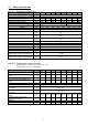
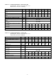
Tab. no. 3 Technical parameters – hard coal as fuel granularity 20 – 40 mm, fuel moisture max. 15 % -1 Calorific value of fuel: 26 - 29 MJ.
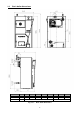
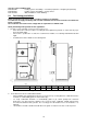
1.4 Basic boiler dimensions L L1 D mm mm mm 3 714 480 4 825 591 Fig. no.
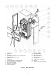
1 2 3 4 5 6 7 8 9 10 11 12 Front cell Center cell Rear cell Feeding gate (with the rosette of primary air) Partition of combustion space Cleaning cover Dump grate Ash gate (with the secondary air flap) Smoke extension piece (tertiary air) Air rosette (tertiary air) Boiler case (complete) Thermo-manometer Fig. no.
Fig. no. 3a) The location of partitions of the combustion chamber Fig. no.
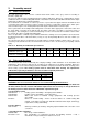
2. Assembly manual 2.1 Boiler construction The main boiler part is the cast-iron sectional boiler drum made of the grey cast-iron according to EN 1561, quality 150. The pressure parts meet the strenght demands according to EN 303-5 - Boilers for central heating – Part 5: Solid fuel boilers for central heating with manual or automatic feed and max. 500 kW nominal thermal output: terminology, requirements, testing and marking.
d) to the system of HWS heating ČSN 06 0320 Heating systems in buildings – Hot water preparation – Designing and planning ČSN 06 0830 Heating systems in buildings – Safety devices. ČSN 75 5409 Water installations inside buildings. 2.3 Positioning possibilities Boiler positioning in the living space (including corridors) is prohibited! A continuous air supply for burning and eventual ventilation must be ensured for the room where the boiler is installed.
Tab. no. 6 Grade of reaction to fire Examples of building materials and products included in the reaction to fire (Extract from EN 13 501-1 + A1) A1 – incombustible Granite, sandstone, concrete, bricks, ceramic tiles, mortars, fireproof plasters, … A2 – combustible with difficulty acumin, izumin, heraklit, lignos, boards and basalt felt, fibreglass boards,... B – hardly combustible Beech and oak wood, hobrex boards, plywood, werzalit, umakart, sirkolit,...
2.4 Delivery and accessories Boiler is delivered according to the purchase order on the pallet, where the whole boiler drum is placed and on the sides it is attached the wrapped boiler shell. The accessories are put inside the boiler drum, accessible by opening the stoking door.
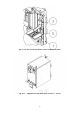
Mounting of covers 1. To take out the covers from the cardboard wrapping. 1 Left side cover part with insulation (3 pcs of connecting spindles, 2 pcs of pivots) Right side cover part with insulation (3 pcs of connecting spindles, 2 pcs of pivots) Upper cover part (4 pcs of spring clips) 2 3 Fig. no.
2. 3. 1 2 3 4 5 6 To fit sheet components with due connecting material according to Fig. no. 6. Connecting spindle 10 pcs Washer 5, 3 Spring clip 10 pcs Washer 8, 4 Screw ST 4, 2x9, 5 10 pcs Screw M5x12 Pivot 6 pcs Screw M8x12 Nut M10 2 pcs Washer 10,5 Nut M5 1 pc Magnetic element According to the Fig. no. 7 – to cover the boiler.
Fig. no. 7 The boiler sheathing 4. 5. To equip the side part with connecting spindles and pivots. To mount on the anchor bolts the side covers parts. To screw with use of nut M10 (2 pcs) and washer 10, 5 (2 pcs) in the upper part the console of the side cover part on the anchor bolts. 6. To mount on the brace the consoles of brace with use of screws M5x12 (detail F).
13. 14. 15. 16. 17. To insert the keeper pin and to fit the washer 10,5 into the partition of the smoke extension piece. To mount the pull rod on the partition of the smoke extension piece and to secure it with the washer 10,5 and the keeper pin - To screw up the nut M 10 on the pull rod. To equip the upper cover part with 4 pcs of spring clips and to fit them on the side cover part. To screw up the rear cover part with use of 10 pcs screws ST 4, 2x9, 5.
2.6 Boiler commissioning This boiler can only be commissioned by a professional assembly firm authorized to do this activity. 2.6.
Usage The two way safety vent DBV 1 – 02 is used as a protection of heating boilers against overheating. In the valve body there is the bleed and supply valve controlled by thermostatic element. When the limit temperature is reached, the bleed and supply valve is simultaneously opened meaning that the cold water is running in and the hot water is running out. When the temperature drops below limit, the bleed and supply valve is simultaneously closed. Caution! It is not a compensation for safety valve.
vent it is necessary to check, if the 3/4“ socket usage, which can be both in pipeline and on boiler, ensures complete immersion of the thermostatic vent element after the vent installation. After the vent has been installed in socket, connect the down pipe, in which the hot water from boiler will flow to drain, to „C“(see. fig. no. 9). The cooling water inlet, which will cool the boiler after setting the vent in operation, is connected (see fig. No. 10) to „A“ (see fig. no. 9).
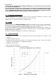
3. Manual for operation 3.1 Boiler operation by user SOFT COAL The most suitable fuel is sort coal with 20 – 40 mm granularity. Burning time at nominal output is 4 hours. HARD COAL The most suitable fuel is hard coal of 20 – 40 mm granularity. Burning time at nominal output is 4 hours. COKE The most suitable fuel is coke of 20 – 40 mm granularity Burning time at the nominal output is 4 hours. ADDITIONAL FUEL – WOOD Using this fuel it is not reached the nominal output. Z O I. II. III.
10. When the fuel starts burning well, stoke another fuel up to the lower edge of the stoking door. During stoking the fuel, do not fill the short circuit hole. For proper function of the boiler it is necessary that the partition of the smoke adapter closes tightly (see chap. 2.6.1 item c). 11. After closing the stoking door close the partition of smoke adapter by means of the draw bar of smoke control. Thus the shorting opening is closed.
3.2 Boiler cleaning - maintenance 1. Ash from ash pan and small ash pan has to be removed in the boiler operation even several times a day according to the type of used fuel, because full ash pan protects the correct division of the combustion air under fuel and evokes rough burning of fuel on grate. Al residues in the boiler furnace, mainly cinder have to be removed before each new burning start and in course of the morning boiler operation reinsertion.
1 2 3 4 5 6 Fig. no. 15 3.3 Front left cover part Nut M8 Washer 8, 4 Assembly spanner Cleaning covering Hexagon socket spanner with handle Dismantling of the cleaning covering IMPORTANT NOTICE 1. The boiler only can be used for the purpose that it is destined for. 2. The boiler can be operated only by adult persons acquainted with this operation manual. It is inadmissible to leave the children unattended by adults near the boiler.
we recommend to operate the boiler at the temperature of 60 C and higher. Possible corrosion marks on boiler drum don´t mean a defect and they don´t affect the boiler function. 11. After the heating season termination it is necessary to clean the boiler, smoke-flues and smoke adapter properly. Spread the graphitic grease on swivel taps, smoke flap mechanism and on other flexible parts of boiler. Keep the boiler room clean and dry. 12.
5. Guarantee and the liability for defects VIADRUS a.s. provides the guarantee: – For boilers 24 months after the boiler putting into operation, but maximum 30 months after the date it was dispatched from the VIADRUS a.s.; – For boiler drum 5 years after the date its dispatch from the VIADRUS a.s. In case of possible complaint of boiler shell, the customer is obliged to sumit the packing label of the boiler shell. It is placed on the cardboard, in which the shell has been dispatched.
Information for customer Packaging identification Assessment reference PE Plastic sacks, folie, corrugated board, iron and plastic fix line Identification of principal materials used. Paper, Polyethylene, iron, wood Part 1: Summary of assessment Standard/Report Assessment requirement 1.1 Prevention by source reduction 1.2 Heavy metals and ensure below maximum permitted levels for components (CR 13695-1) 1.
Annex to the guarantee certificate for customer- the user Record of accomplished guarantee and post-guarantee repairs and regular product checks Record date Contracting service organization (stamp, signature) Carried out activity 27 Customer´s signature
VIADRUS HERCULES U 24 VIADRUS a.s. Bezručova 300 | 735 81 Bohumín telefon: 596 083 050 | fax: 596 082 822 mail: info@viadrus.cz | www.viadrus.