HEAVY DUTY ONBOARD AIR SYSTEM Thank you for purchasing this complete, self-contained onboard air system. Contained in one package, you’ll find everything you’ll need to install a high performance, onboard air source for your vehicle. Please follow these instructions to install your new system. OBA Components: 1 - 2.5 Gallon, 6 port VIAIR Air Tank 1 - 400C model VIAIR compressor 1 - 36-ft.
HEAVY DUTY ONBOARD AIR SYSTEM PARTS PACKAGES REDUCER Package #1 – Air Tank Installation: A BCD F G BB H I J Mounting Bolts (4pcs) Flat Washers (8pcs) Locking Washers (4pcs) Nuts (4pcs) Rubber Tank Mount Bushings (6pcs) 1/4” NPT Drain Cock (1pc) 1/4” NPT 175 PSI Safety Valve (1pc) 1/4” NPT Compression Fitting (3pcs) 1/4” NPT F Quick Connect Coupler (1pc) 1/4” NPT F Quick Connect Stud (1pc) Package #4 – Gauge Panel Installation: REDUCER CER L MN R U O S P W 1 2 5 HH II 0 30 35 0
HEAVY DUTY ONBOARD AIR SYSTEM P/N 10005, 10007 2.5 GALLON AIR TANK & PLUMBING (USE CONTENTS OF PARTS PACKAGE #1) OBA PLUMBING DIAGRAM Typical System Configuration, May Vary Depending on Installation Your 2.5 Gallon air tank comes with six 1/4” NPT port openings to allow installation in many configurations on your vehicle. To ensure safe and trouble-free use of your air tank, we strongly recommend that you install the supplied drain cock and a safety pressure relief valve.
HEAVY DUTY ONBOARD AIR SYSTEM 400C AIR COMPRESSOR INSTALLATION (USE CONTENTS OF PARTS PACKAGE #2) Your Heavy Duty Onboard Air System comes complete with a 400C, 33% duty cycle compressor. Please follow the installation instructions that follow to enjoy the best use of your onboard air system. CAUTION - To reduce risk of electrical shock or electrocution: - Do not disassemble the compressor. Do not attempt repairs or modifications. Refer to qualified service agencies for all service and repairs.
HEAVY DUTY ONBOARD AIR SYSTEM 400C OPERATING INSTRUCTIONS IMPORTANT: The 400C has a maximum working pressure of 150 PSI and is capable of 33% duty cycle. Always operate the compressor at or below the MAXIMUM PRESSURE RATING of the compressor. Operation exceeding maximum pressure ratings and or duty cycle will result in damage to air compressor. 1. Your air compressor is equipped with an AUTOMATIC THERMAL OVERLOAD PROTECTOR.
HEAVY DUTY ONBOARD AIR SYSTEM DASH PANEL GAUGE INSTALLATION (USE CONTENTS OF PARTS PACKAGE #4) Your VIAIR Heavy Duty Onboard Air System comes complete with a Dash Panel Gauge to monitor the pressure of your 2.5 gallon VIAIR air tank. Additionally, the Dash Panel Gauge has an ON/OFF switch preinstalled that will allow you to turn the system off by cutting power to the pressure switch with relay that you have already installed.
HEAVY DUTY ONBOARD AIR SYSTEM DASH PANEL GAUGE INSTALLATION (CONT’D) 5. Wiring the Dash Panel Gauge for Illumination: There are two wires, one red and one black connected to the light bulb of the gauge. Connect the red wire to a suitable fused dash panel circuit. Use the quick splice connector included in the kit for wire connections. The black wire is to be connected to a suitable ground source. 6.
HEAVY DUTY ONBOARD AIR SYSTEM TROUBLESHOOTING GUIDE: PROBLEM POSSIBLE CAUSE(S) CORRECTIVE ACTION Tank pressure drops when compressor (s) shut off 1. Loose drain cock 2. Check valve leaking 3. Loose connections 1. Tighten drain cock 2. Replace check valve or compressor(s) 3. Check all connections with soap and water solution and tighten Compressor runs continuously and air flow lower than normal 1. Excessive air usage 2. Loose connections 3. Worn piston ring or inlet valve. 4.
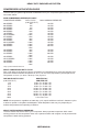
HEAVY DUTY ONBOARD AIR SYSTEM COMPRESSOR APPLICATION GUIDE To ensure that you get the highest level of satisfaction from your compressor performance, refer to information below: VIAIR COMPRESSOR REFERENCE CHART COMPRESSOR SERIES DUTY CYCLE MAX.
HEAVY DUTY ONBOARD AIR SYSTEM AMERICAN WIRE GAUGE GUIDE 12-VOLT: Amp Draw Length of wire from battery to compressor (in feet) 5 10 15 20 25 30 40 50 60 5 16 16 16 14 14 12 12 10 10 10 16 14 12 10 10 10 8 6 6 15 16 12 10 10 8 8 6 6 4 20 14 10 10 8 6 6 6 4 4 P/N 10003, 10005, 10007, 20001 COMPRESSOR WIRING DIAGRAM (with combination pressure switch / relay) Wiring Diagram: (Figure 2) To Lamp Circuit Dash Panel To Keyed Power Source White Black Small Red Large Red Fuse - + Battery 15 Edelman Irv
LIMITED WARRANTY: VIAIR Corporation warrants this product, when properly installed and under normal conditions of use, to be free from defects in workmanship and materials for a period of one year from its original date of purchase. To receive warranty service or repair, please contact VIAIR Corporation. Returns should be made within one year of the date of purchase, after a Return Goods Authorization (RGA) number has been assigned by VIAIR Corporation.