
Specifications


SurfBeam Satellite Modem Installation and Configuration Guide
Rev. B VSD-200292-02-085
3
-
7
3. Satellite Modem Indicators
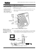
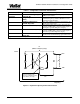
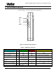
Figure 3-1 shows the indicators on the satellite modem’s front panel.
Refer to Table 3-1 for a description of the indicators.
Figure 3-1 SM Front Panel Indicators
?
Table 3-1 SM Indicator Functions
Function Indicator Conditions
PWR
RX TX LAN
1
Power is not applied OFF
OFF OFF OFF
Power is applied (startup) ON
OFF OFF OFF
Power is applied
(after startup)
ON
OFF OFF ON - CPE connected to Ethernet
OFF - CPE not connected to Ethernet
SM acquiring Downstream ON
“slow” blink
(1-second period)
OFF ON - CPE connected to Ethernet
OFF - CPE not connected to Ethernet
Ranging/registration in
process
ON
“fast” blink
(½-second period)
FLASH during
upstream traffic
ON - CPE connected to Ethernet
OFF - CPE not connected to Ethernet
SM successfully
ranged/registered (normal).
ON
ON FLASH during
upstream traffic
ON - CPE connected to Ethernet
OFF - CPE not connected to Ethernet
Fault as a result of POST ON
“very fast” blink
(1/8-second period)
N/A N/A
1
If CPE is turned off, LAN indicator will not light.
PWR
RX
TX
LAN