
User Manual

31
5. Repeat steps 3 and 4 for each potential leak point in the suspect loop.
6. Tighten or remake any connection or joint that has been found to be leaking.
Replace any component whose leak cannot be stopped by the tightening or
remaking process.
7. Rerun the overall system leak checking procedure called out earlier in this
section to ensure that all the leaks in the loop have been identified and repaired.
8. Using clean, lint-free rags, carefully wipe up any residual leak detection fluid
from the interior of the Dynacalibrator cabinet.
Component Isolation Method
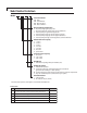
1. Remove the top cover of the unit by unscrewing the six allen screws on each
side of the instrument, above the side bars..
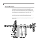
2. Trace out the internal plumbing loop that has been found to be leaking, starting
at the point where the leak checker gauge has been connected and ending
at the point where the air source has been connected. Be sure you have not
overlooked any fitting, joint, or other possible point of leak in this loop. (The
loop is the entire set of internal plumbing that was subjected to the leak
checking charging pressure of 20 inches of water.)
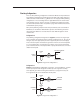
3. Starting at the air source end of the suspect loop, break a fitting and, using an
appropriate adapter, connect the leak checker gauge to the upstream side of
the disconnected joint.
4. Open the valve on the air source and slowly charge the unit until the gauge
reads 20 inches of water. Close the valve on the air source.
5. Monitor the gauge for at least 30 seconds. If the reading does not change,
there are no leaks in this path to this point. Proceed to Step 7. If the reading
drops, then a leak between the air source and the leak checker gauge can be
inferred.
6. Tighten or remake any connection or joint that is upstream of the leak
checker gauge. Repeat steps 4, 5, and 6 until no further leaks are indicated,
then proceed to step 7.
7. Once a section of the loop has been determined to be leak free, go to the
next fitting downstream of the point of the previous check and repeat the
previous procedure starting at step 3 above. When the end of the loop has
been reached by the previous sequential troubleshooting procedure, this
check can be considered completed. For reference, the end of the loop is the
point where, in the initial leak checking procedure, the Leak Checker gauge
was placed.
8. Once the task has been completed and all leaks eliminated, close the
instrument up and return it to use.