
Manual


29
Appendix: PD-C2 Controller (shipping February 2014)
If you have been directed to this part of the manual, you are probably
replacing an older PD-C2 controller or have received a new Pulsed
Discharge Detector with the latest design. If that is the case, congratula-
tions. You have the latest and greatest controller as a component of a truly
remarkable detector system. Functionally, this controller does everything
that our previous version did, but the new one does it with less power,
greater efficiency, and fewer parts.
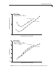
There are some minor changes to the rear panel connectors in this most
recent version of the PDD controller. (Figures 9 and 10) The same signal
outputs are provided, but they are now all accessed through one output
connector.
ATTENUATED OUTPUT
The attenuated signal is normally connected to a strip chart recorder or
similar recording device. This output is designed for a 1mV full scale strip
chart input. There is also an internal signal reference (-) at zero volts. For
best noise performance, the shield (earth) and signal reference (-) should
not be connected together. The signal from this output is scaled by the
attenuation factor set on the front panel.
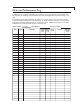
Figure 9: Rear panel of the control module