Valco Instruments Co. Inc. Digital Valve Sequence Programmer Instruction Manual MAN-DVSP Rev. 1/93 Printed in USA P. O.
Table of Contents 1. GENERAL DESCRIPTION...............................................................................1 2. IMPLEMENTATION...........................................................................................2 2.1 Solenoid Valves 2.11 110 VAC 2.12 12 VDC 2.13 Valco MSVA 2.14 Pulsed Operation of Solenoids 2.2 Valco Electric Actuators 2.21 Multiposition 2.22 Two position 2.3 Valco Digital Valve Interface (DVI) 3. SWITCH AND DISPLAY FUNCTIONS ...............................................
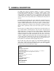
1. GENERAL DESCRIPTION The Digital Valve Sequence Programmer (DVSP) is an add-on or stand-alone timer/programmer available with either 2 or 4 intervals, settable in ranges of 0-99 seconds, 0-9.9 minutes, or 0-99 minutes.
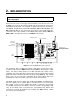
2. IMPLEMENTATION Before removing the top cover of the DVSP, make certain that the power cord is unplugged. Remove the two screws on the upper rear panel which secure the top cover. Look at Figure 1 to locate the two barrier terminal strips located near the center of the large printed circuit board. The terminals are grouped beside letters denoting relays A, B, C, and D, and are marked C for Common, NO for Normally Open, and NC for Normally Closed.
The table below indicates which group of terminals applies to each interval for the various DVSP models. In the drawings which illustrate the different wiring options, the terminal groupings are chosen purely for convenience: there is no intent in these drawings to convey any information about specific intervals. DVSP-2 Interval 1 Relay A DVSP-4 Interval 2 Interval 1 Relay C Relay A Interval 2 Relay B Interval 3 Relay C Interval 4 Relay D 2.1 Solenoid Valves 2.
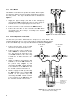
2.13 Valco MSVA The MSVA is used with a two position air actuator, which requires one interval to switch to the inject position and another to switch to the load position. The steps described below are illustrated in Figure 3. 1. Supply the proper voltage (110 VAC in this example) by connecting the HOT terminal to C of the one of the groups of terminals to be used, and jumping it to C of the other. 2. Connect one wire of each solenoid to the NEUT terminal. 3.
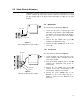
2.2 Valco Electric Actuators Multiposition actuators require only one event to step the valve/actuator to its next position. However, the two position actuator requires two intervals: one to switch the two position valve to its inject position and another to switch it to its load position. 2.21 Multiposition The steps below are illustrated in Figure 5. GREY WIRE WHITE WIRE 1. Locate the two pairs of adjacent grey and white wires in the interface cable supplied with the actuator.
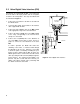
2.3 Valco Digital Valve Interface (DVI) Two intervals are required with the DVI: one to signal it to move the valve to the inject position, and one to signal it to return to the load position. The steps described below are illustrated in Figure 7. DIGITAL VALVE INTERFACE 1. Connect the air actuator to the DVI as described in the DVI literature. 2. Locate the blue, black, and red wires in the interface cable supplied with the DVI. 3.
3. SWITCH AND DISPLAY FUNCTIONS 1. Power ON/OFF: Turns the DVSP on and off. 2. Interval duration switches: Each interval has two thumbwheel switches for setting the the interval duration, in increments determined by the setting of the time unit switches. 3. Time unit switches: Under each pair of interval duration switches is a three-position switch which defines the units in which the duration is set.
4. DEMONSTRATION SEQUENCE This example demonstrates use of the DVSP-4 to control the positioning of two Valco switching valves. Valve 1 (V1) is used for sample injection and Valve 2 (V2) is configured for column backflushing. Both valves are air actuated, but V1 is controlled by a Valco Digital Valve Interface (DVI) while V2 is controlled by a pair of 3-way solenoid valves (MSVA). Each valve requires two intervals of the DVSP; one for clockwise rotation and one for counterclockwise.
Valco Instruments Co. Inc. m s m x .1 1 m s m x .1 2 m s m x .1 3 m s m x .1 4 AUTO RUN POWER Figure 11: DVSP front panel programmed for the demonstration process Programming the DVSP is very simple now that the process has been broken into steps: 1. Set the switch beside the "1" to the right, for "seconds", and set the thumbwheel switch to 02. 2. Set the switch beside the "2" to the left, for "minutes", and set the thumbwheel switch to 15. 3.
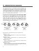
VALVE 1 VALVE 2 INTERVAL 2 INTERVAL 4 INTERVAL 3 INTERVAL 1 4 2 3 AIR IN 1 AIR IN BLACK WIRE RED WIRE BLUE WIRE TERMINALS FOR RELAY "E" WITH TWO SECOND PULSE Figure 12: DVSP connections for the demonstration process 10
5. TECHNICAL DRAWINGS Digital Valve Sequence Programmer Assy .................. Drawing 21143 Page 12 Mother Board Assy, Four Interval DSVP ..................... Drawing 21027 Page 13 Schematic - DVSP Mother Board ................................ Drawing 21212 Page 14 Logic Board Assy ......................................................... Drawing 21061 Page 15 Schematic - Logic Board.............................................. Drawing 21030 Page 16 Digiswitch Interface Board Assy............
1 21 21 27 2 13 12 E F 8 FOR 220 VERSION COVER SILKSCREEN w/220 VAC TAG 9 m 18 19 7 CONNECTIONS 23 s mx.1 7 7 1 m s mx.1 1 1 2 m mx.1 s 7 7 3 m mx.1 1 s VOLTS S/N DIGITAL VALVE SEQUENCE PROGRAMMER BOARD NO 21060 ** 50/60 Hz ** FUSE 2A 120 VAC 11 E US F US 12 E FUS 1 3 4 6 Made in USA AUTO ADV 22 RUN RST 5 10 4 25 STOP 11 BLK POWER Valco Instruments Co. Inc.
13 Valco Instruments Co. Inc. S1 CO2 L1 CO5 CO1 VIEW A-A INSTALLED ON BACK OF BOARD S2 R5 A A RN1 REG RN2 CO6 L2 C6 C3 S3 C2 C1 L3 Z2 S4 L4 R1 CO10 CO8 INSTALL MICA INSULATOR UNDER S3 AND S4 Z4 CO4 CO3 PCB L5 CO11 CO9 NW R2 R3 R4 L6 RA RLY2 RLY1 C4 CO12 MT SC NUT CO7 T1 RLY3 RLY4 C5 B-21143 REVISIONS DESCRIPTION DATE SUB-DIR \DVSP\ FILE NAME 1/5/97 DATE 21027 CHECKED DESIGNED R.B.D.
14 CO5 6 5 7 4 2 1 3 +12 15 14 13 12 11 9 8 10 TO TWS ASSY I-21025, 27 SCHEMATIC - 21294 OR 21296 1 2 3 4 5 6 7 8 9 10 11 12 13 14 15 16 17 18 19 20 16 RN1 (Z1) C06 +12 1 2 3 4 5 6 7 8 9 10 PLS 2 MIN SEC PULSE PULSE RUN LT XST START STOP M8 M4 M1 M2 L8 L4 L1 L2 CO7 ADV AUTO XCNT ADA ADB XSTOP XHOLD RST AUTOLT OUT2 OUT1 OUT4 OUT3 GND +12 POR CLOCK DP XHOLD RESET LOGIC BOARD ASSY 21061 SCHEMATIC- 21030 TO PUSHBUTTON ASSY I-21059 SCHEMATIC- 21062 R2 1.
15 I-IC4018 I-IC4020 I-IC4049 RES: 100 K, 5%,1/4W CAP: CERAMIC,.022 uF,50V,.250 LEADS CAP: TANAL,.47 MF 35V CAP: CERAMIC VARIABLE, JFD-DV2PS120D CAP:TANTAL, 47MF 35V CAP: CERAMIC 47pf 1000V CRYSTAL: 2.
R14 100K 11 13 CK 10 Q R 8 12 Q S D 9 Z10 1/2 4013 11 13 CK 10 Q R 8 12 Q S D 9 Z16 1/2 4013 6 Z21 7 4049 5 Z5 6 4093 2 Z21 3 4049 SPARES OUT3 33 OUT4 32 OUT1 31 OUT2 30 RESET 40 PLS2 1 PULSE 5 PULSE 4 128 HZ 8 XCNT 23 +12 4 Z21 4049 R13 10K .
17 S1 L1 CO1 Z1 S2 L2 Z2 CO2 CO3 S3 L3 Z3 C1 S4 INSTALL ON OPPOSITE SIDE L4 R1 PCB REVISIONS C03 C01,2 C1 DATE I-T6092007 I-T09523101 I-CC223-50 I-R511001 I-SW-7103MD I-LED550-01 I-IC4072 I-RN761-1-220K I-IC4049 I-PCB21087 PART # 06/15/99 APPROVED 1 EA 2 EA 1 EA 1 EA 4 EA 4 EA 1 EA 1 EA 1 EA 1 EA QTY JDURR SUB-DIR \TGA\ FILE NAME 06/15/99 DATE 21088 CHECKED DESIGNED JDURR DRAWN APPROVED TOLERANCES UNLESS 63 OTHERWISE SPECIFIED FRACTIONS DEC. ANGLES .X.
18 16 Z2 220K 3 6 8 14 1 11 12 7 2 4 15 5 9 13 10 S1 INT 1 M S S2 INT 2 M S3 INT 3 M ADD JUMPER S S S4 INT 4 M 10 2 4 6 9 3 5 7 8 15 12 1 11 4049 Z1 +12 7 Z3 4072 14 S 9 11 12 10 4 3 5 2 14 +12 L1 1 SEC 13 MIN C1 L2 .02 uF L3 L4 R1 1.
19 PCB SEE NOTE 1 CONNECTOR SO2 DISP2 ADV P.C. BOARD SO1 DISP1 SW1 RN1 AUTO Z1 RST Z2 RUN 10 4 DVSP 2 DVSP 2 EA. 2 EA. 1 EA. I-IC40110 I-SW-21206 IC: DES. UP/DN CNTR W/ 7 SEG OUTPUT SWITCH: PUSHBUTTON, ADV-AUTO-RST SCHEMATIC B-21062 Z1-2 SW1 REF. ,C-21721 B-21143 B-21141 B-21142 SUB-DIR \DVSP\ FILE NAME 6/15/89 DATE 21059 CHECKED DESIGNED J.H. DRAWN APPROVED TOLERANCES UNLESS 63 OTHERWISE SPECIFIED FRACTIONS DEC. ANGLES .X.1 1/64" 1 .XX.01 .XXX.
20 5 9 8 10 UNITS 40110 Z1 16 ADV CO1 1 15 14 13 12 3 2 7 4 3 2 1 5 6 10 9 8 7 6 5 RESET RESET GND 4 12 4 CLOCK COUNT RESET 3 AUTO SW1 14 13 DISP1 8 7 DISPLAY 6 1 MAN 74 2 +12 V AUTO 2 8 11 12 13 14 10 9 RUN ADVANCE 1 1K RN1 STOP DEC POINT 5 9 8 RUN TENS 40110 Z2 16 1 15 14 13 12 3 2 SW2 14 10 9 11 8 12 13 A REVISIONS 1K RN2 1 5 6 4 7 3 2 12 4 DATE 06-04-99 VALID FOR PCB ASSY I-21059 REV B-C STOP 9 14 13 DISP2 8 7 DISPLAY 6 1 MAN 74 2 CONVERT F
21 0 PCB SOC4 EC 0 8 EA I-SW29CAP END CAP: SWITCH 29-06001-89 SCHEMATIC B-21294 EC REF. DVSP 4 8 EA. I-SW29118P SWITCH: THUMBWHEEL, BCD SW B-21143 ,C-21721 DRAWN 8 EA I-SW29ST2 STRAP: 2 WIDE 29-57001-2 ST NEXT ASSY. APPROVED 2 EA. I-T09641101 JDURR SUB-DIR \DVSP\ FILE NAME 06/14/99 21023 CHECKED DESIGNED DATE TOLERANCES UNLESS 63 OTHERWISE SPECIFIED FRACTIONS DEC. ANGLES .X.1 1/64" 1 .XX.01 .XXX.005 4 EA.
22 3 13 6 8 7 9 10 +12 THREE INTERVAL MODELS- OMIT S4 3 16 13 +12 1 2 4 8 C 1 3 13 1 1 2 4 8 C CO2 6 8 7 Z3 4052 APPLIES TO ASSY 21021, 21022, 21024, REV B PCB 9 10 INT 3 S3 13 6 8 7 Z4 4052 9 10 S4 DATE 1 2 4 8 C 1 UNITS 06/15/99 APPROVED +12 JDURR SUB-DIR \TGA\ FILE NAME 06/16/99 DATE 21294 CHECKED DESIGNED JDURR DRAWN APPROVED TOLERANCES UNLESS 63 OTHERWISE SPECIFIED FRACTIONS DEC. ANGLES .X.1 1/64" 1 .XX.01 .XXX.
6. WARRANTY This Limited Warranty gives the Buyer specific legal rights, and a Buyer may also have other rights that vary from state to state. For a period of 365 calendar days from the date of shipment, Valco Instruments Company, Inc. (hereinafter Seller) warrants the goods to be free from defect in material and workmanship to the original purchaser.