
Manual
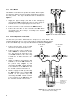
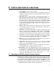

2.13 Valco MSVA
The MSVA is used with a two position air actuator, which requires
one interval to switch to the inject position and another to switch to
the load position. The steps described below are illustrated in
Figure 3
.
1. Supply the proper voltage (110 VAC in this example) by
connecting the
HOT
terminal to
C
of the one of the groups of
terminals to be used, and jumping it to
C
of the other.
2. Connect one wire of each solenoid to the
NEUT
terminal.
3. Connect the other wire of each solenoid to the
NO
s which
correspond to the
C
s of Step 1, according to the desired
switching sequence.
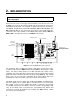
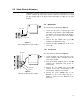
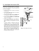
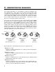
2.14 Pulsed Operation of Solenoids
The first three procedures demonstrate the simplest uses of the DVSP. This
example will illustrate the use of the pulsed relay in conjunction with two devices
on the same DPDT relay. The steps described below are illustrated in
Figure 4.
1. Connect the two wires of the 12 VDC
solenoid as described in Section 2.12.
2. Connect one wire of the 110 VAC sole-
noid to
NEUT
as described in Section
2.11, but connect the other wire to the
second
NO
terminal of the
same
relay
to which the 12 VDC solenoid is con-
nected.
3. Supply 12 VDC by connecting the
+12
terminal to one of the
NO
terminals on
the pulsed relay (
Figure 1
) and
connecting that
NO
’s related
C
ommon
to the
C
ommon of the
NO
which has
the 12 VDC solenoid connected to it.
4. Likewise, supply 110 VAC by connecting
the
HOT
terminal to the remaining
NO
terminal on the pulsed relay and
connecting that
NO
’s related Common
to the Common of the
NO
which has
the 110 VAC solenoid connected to it.
12 VDC SOLE-
NOID
110 VAC SOLE-
NOID
TERMINALS FOR
EXTRA RELAY
WITH TWO SEC-
OND PULSE
Figure 4:
Use of the pulsed relay and
two events on one relay
Figure 3:
110 VAC Valco MSVA
4