Valco Instruments Co. Inc. Instrumentation Temperature Controller Instruction Manual MAN-ITC Rev. 8/96 Printed in USA P. O.
Table of Contents Page 1. GENERAL DESCRIPTION..............................................................................1 1.1 Standard Features 1.11 Thermocouple Sensor 1.12 Proportional Heater Power Control 1.13 Power Attenuation 1.14 Zero Crossover Power Application 1.15 Digital Temperature Setting 1.16 Compact Rugged Construction and Functional Layout 1.2 Specifications and Model Codes 1.3 Technical Description 1.31 Thermal System Overview 1.32 ITC Block Diagram by Function 1.321 Input Amplifier 1.
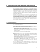
1. INTRODUCTION AND GENERAL DESCRIPTION The Instrumentation Temperature Controller (ITC) is an isothermal temperature controller intended for broad spectrum usage in thermal systems common to modern analytical instrumentation. The instrument is designed to be a flexible building block with which the user can configure a thermal system to suit particular requirements.
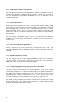
1.12 Proportional Heater Power Control The ITC utilizes proportional power application to minimize temperature overshoot, and improve temperature stability about the setpoint. Controls are accessible to the user, allowing the proportioning bandwidth (in oC) to be adjusted to meet specific requirements. 1.13 Power Attenuation Many temperature controllers are used in conjunction with variacs (variable output transformers) in order to improve temperature stability.
1.2 Product Numbers and Specifications Product Numbers: ITC10X X corresponding to 399 for 0°C to 399°C range 999 for 0°C to 999°C range Example: ITC10399: ITC, 1000 watts maximum heater power, 0°C to 399°C range Sensor Requirement Thermocouple; Type K Range 0° to 390°C, or 0° to 999°C, as ordered Absolute Accuracy ±.5% of full scale Repeatability .5°C at constant ambient Sensititivity to Ambient Changes .
1.3 Technical Description A general knowledge of the ITC’s organization and operation is helpful to its successful implementation. To facilitate understanding, three questions are posed: 1. What position does the ITC occupy in a thermal system? 2. How is the ITC organized to accomplish its task? 3. What is the most important aspect of the ITC’s organization? These questions are answered by Sections 1.31, 1.32, and 1.33, respectively. 1.
It is readily seen that the ITC is responsible for maintaining the temperature within the heated zone. However, proper selection and application of the thermocouple and heater are essential if the ITC is to perform its function. (Refer to Section 2.2.) 1.32 ITC Block Diagram by Function Almost any electronic device can be described by a block diagram of its circuit elements, each element performing something essential to the function of the device.
1.323 Differential Comparator A differential comparator is used to compare the output of the D/A converter with that of the input amplifier. Subsequently, the comparator’s output denotes whether the zone temperature is higher or lower than the setpoint. 1.324 Heater Power Switch In accordance with the comparator’s decision, the power circuitry will apply power to the heater when the zone temperature is below the setpoint and interrupt power when it is above the setpoint.
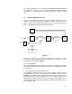
If zone heater power is simply applied or interrupted according to the comparator’s verdict (correction required/not required) the result is wholly unacceptable. To illustrate: Assume that a zone is to be heated from room ambient to 75o C. If 100% power is applied until the temperature reaches 75o, and then interrupted, the temperature will overshoot. As the temperature settles back to 75o, 100% power will again be applied in an effort to prevent the temperature from falling below the setpoint.
1 2 3 102° PROPORTIONING WAVEFORM 98° POWER APPLICATIONS TIME 1 CONTROLLED TEMPERATURE RISING FROM AMBIENT; NOTICE POWER APPLICATION IS PROGRESSIVELY REDUCED AS THE TEMPERATURE RISES 2 OVERSHOOT; NO POWER APPLIED 3 EQUILIBRIUM;CONTROLLED TEMPERATURE HAS SETTLED AT APPROX. 40% POWER Figure 4 The number of degrees between the upper and lower temperature boundaries is referred to as the proportioning bandwidth.
In summary, the proportioning circuitry determines the percentage of time during which power will be applied, while the attenuation circuitry determines what percentage of power is to be available for delivery during this time.
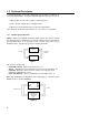
2. OPERATION In this section practical considerations for the ITC’s usage are discussed. 2.1 Physical layout of the ITC Following are illustrations of the various models of the Instrumentation Temperature Controller. Figure 5 shows the front panel, and Figure 6 shows the top view of the ITC. Figures 7 and 8 show the back panels of the 110V AC and 220V AC models. The numbers on the illustrations relate to the numbered parts below.
10 8 9 7 7 Figure 6: Top view, model ITC10 8 Thermocouple Connector Printed circuit board mounted connector; connect red lead of thermocouple to Terminal R. 9 .5 Amp Fuse Printed circuit board mounted; fuses power supply primary circuitry. 10 10 Amp Fuse Printed circuit board mounted; fuses heater power circuitry.
11 Heater Receptacle, 120V AC only Rear panel mounted AC receptacle; two-wire plus ground; connects heater via standard 16 or 18 gauge three-wire power cord (not supplied). 12 Heater Receptacle, 220V AC only Rear panel mounted AC receptacle; two-wire plus ground; connects heater via power cord (black and white to heater, green to ground). Power cord is not supplied. 13 Top Cover Retaining Screws Remove these screws to gain access to interior of ITC. 2.
1. The measuring junction should be of the lowest mass practicable for the application. Simply put, the higher the mass, the more time required for the junction to reach the temperature of its surroundings. 2. The measuring junction should be placed as close as possible (thermally) to the heater. Whenever there is doubt about proper location of a thermocouple, follow these suggestions: a. Place the junction directly between the heater and the object to be heated, as close to the heater as possible. b.
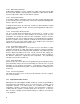
2.4 Proportioning Bandwidth Note: Current models of the ITC may have fixed valued resistors in the trim pot location for the bandwidth calibration. If the ITC needs further calibration they may be replaced with 10K trim pot and the following text will explain the band width adjustments. Given that the controlled temperature is reasonably accurate, stability becomes a most important measure of system performance.
POWER APPLICATIONS CONTROLLED TEMP 3° 1° EXCURSION TIME POWER APPLICATIONS CONTROLLED TEMP 1° EXCURSION 6° CONTROLLED TEMP EXCURSION TEMP Figure 9 power is increased too abruptly, quickly driving the temperature up, out of reach. If the heater size cannot be reduced, the bandwidth must be increased. Doing so will decrease the rate of change in applied power, hopefully increasing stability. Always allow ten to fifteen minutes after making each adjustment before making another.
2.5 Installation The following discussion is intended to assist you in the initial installation of an ITC. It is assumed that you have read the foregoing portions of this manual. Check the instrument for shipping damages. Open the instrument and check for loose components. There shouldn’t be any. In the event that damage is noted, notify the carrier immediately. Valco assumes no responsibility for damage incurred in shipment. Assuming no damage is seen, perform the following checkout.
connected to AC ground. Failure to do so may cause a shock hazard, or controller malfunction, or both. Locate the ITC where it will not be subjected to abrupt changes in ambient temperature. This will improve the controlled temperature stability. When installing the thermocouple, be sure to observe electrical restrictions noted in Section 2.2. Actual installation consists of, first, thinking about what must be done, then connecting the heater, and finally inserting the thermocouple.
2.63 Situation: No power being applied to heater; TCPL indicator OFF. In this situation, the HTR indicator remains OFF. The power triac is protected against continuous current overload with a 10 amp fuse. (Refer to Figure 6, Item 11.) If this fuse is blown, no power is available to the heater circuitry. In addition to replacing a blown fuse, consider what may have caused the overload. The heater and/or power triac may have developed a short circuit.
3. WARRANTY This Limited Warranty gives the Buyer specific legal rights, and a Buyer may also have other rights that vary form state to state. For a period of 365 calendar days from the date of shipment, Valco Instruments Company, Inc. (hereinafter Seller) warrants the goods to be free from defect in material and workmanship to the original purchaser.
4. TECHNICAL DRAWINGS Assembly Drawing ................................................................................Drawing 21556 Page 21 Assembly Broad Drawing .....................................................................Drawing 22218 Page 22 Schematic – ITC Board ........................................................................Drawing 22219 Page 23 Board Conversion .................................................................................
* REVISIONS 220V VERSION ONLY LTR 19 4 7 8 13 12 20 * 5 18 2 4 Instrumentation Temperature Controller Instruction Manual YELLOW 17 RED 16 * 15 Valco Instruments Co. Inc. GREEN 110V VERSION 3 BLACK WHITE 14 9 4 18 SEE NOTE 2 GREEN (GREEN/YELLOW 220V) ITEM 1 2 3 4 5 6 7 8 9 10 11 12 13 14 15 16 17 18 19 20 DATE APPROVED ITC BD. ASSY. REV. M,N ENCLOSURE C-21527 REV.
22 REVISIONS ITEM DESCRIPTION VALCO # QTY PCB PCB ASSY: ITC 10 AMP I-PCB22217 1 EA T1 TRANSFORMER 115/230V DSC4-24 I-X-DSC4-24 1 EA F1 FUSE: 10AMP 3AG HWFUSE-10A 1 EA F2 FUSE: 3AG SLO BLO 1/2 AMP (TYPE 313.5) HWFUSE-.
REVISIONS VOLT. READING BANDWIDTH ADJ. 8 9 RN3 10 100K 7 3 11 8 CO2 R6 953 +12V -IN -ALM +IN -V AD 595 COUNT +V FB +ALM V0 13 7 5 6 10 8 9 C13 1MF RN2 100K 9 11 RN2 6 100K R8A 10K RN2 15 100K 2 R8B 715 -12V C11 4 C14 4.7uf -12V -12V Z1 14 1 2 3 4 11 12 RN2 100K 13 6 INITIATED J DURR J DURR R3 2.2Meg R4 10 1/ 2 358 .
LTR A B C DESCRIPTION ITC BD. REV M,N ECN #1808 NEW DWG DATE 21FEB89 15APR94 8AUG94 ECN #2050 SHOW NEW VER. W/R13 & R14 APPROVED J DURR J DURR ASSY-22218 SCH-22219 BD-22217 AW-160 REV-N CUT ADD JUMPER COMPONENT SIDE MT6 SC6 KN6 SW 1 CO3 CO4 CO5 CO6 R13 R14 L1 L2 COMPONENT SIDE NOTE: INSTALL R13 AND R14 ON BOARD FOR 220V VERSION.