SCSI-Fibre Channel Router Installation and User Guide A5814A Distancing Solution A5814A-003 SCSI-Fibre Fabric Connectivity Part Number: A5814-96004 Revision 2.1.0 (September 12, 2001) © Copyright Hewlett-Packard Incorporated 2001. All rights reserved.
Hewlett-Packard SCSI-Fibre Channel Router Installation and User Guide Copyright This document (and the information herein) is the property of Vicom Systems, Inc. It has been reproduced by Hewlett-Packard with the expressed permission of Vicom to meet the purpose for which it was delivered. This document may not otherwise be copied or reproduced in whole or in part, nor used or revealed to any person in any manner except to meet the purposes for which it was delivered.
Hewlett-Packard SCSI-Fibre Channel Router Installation and User Guide Service and Support Please fill out and mail or fax the warranty registration card contained in the SCSI-Fibre Channel Router packing box as soon as possible. Each unit must be registered in order to qualify for technical support. FCC EMC Statement (USA) This equipment has been tested and found to comply with the limits for a Class A digital device, pursuant to Part 15 of the FCC Rules.
Hewlett-Packard SCSI-Fibre Channel Router Installation and User Guide BCIQ EMC Statement & License Number (Taiwan) (TBD) Harmonics Conformance (Japan) (N/A) German Noise Declaration Schalldruckpegel Lp = 50 dB(A) Am Arbeitsplatz (operator position) Normaler Betrieb (normal operation) Nach ISO 7779:1988 / EN 27779:1991 (Typprüfung) Laser Safety A.
Hewlett-Packard SCSI-Fibre Channel Router Installation and User Guide C. Usage Restrictions Failure to comply with these usage restrictions may result in incorrect operation of the system and points of access may emit laser radiation above Class 1 limits established by the IEC and the U.S. DHHS. D.
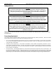
Hewlett-Packard SCSI-Fibre Channel Router Installation and User Guide Safety Notices Danger An electrical outlet that is not correctly wired could place hazardous voltage on metal parts of the system or the products that attach to the system. Verify that the wiring and grounding of the electrical outlets you use have been checked by a licensed electrician. Danger The enclosure should only be opened by authorized service personnel.
Hewlett-Packard SCSI-Fibre Channel Router Installation and User Guide Limited Warranty Terms and Conditions VICOM warrants that its Products will be free from defects in material and workmanship under normal use and service for a period of one year after delivery to the initial end user purchaser, but no longer than eighteen months after the date of shipment by VICOM.
Hewlett-Packard SCSI-Fibre Channel Router Installation and User Guide Table of Contents 1 INTRODUCTION ...............................................................................................................................................................1 1.1 SYSTEM REQUIREMENTS.....................................................................................................................................................1 1.2 SCSI-FC ROUTER CAPABILITIES DEFINED ...............................
Hewlett-Packard SCSI-Fibre Channel Router Installation and User Guide 4.1 GUIDELINES FOR USAGE OF SCSI AND FC CABLING ........................................................................................................19 4.1.1 SCSI Cabling.............................................................................................................................................................19 4.1.2 SCSI Termination.....................................................................................
Hewlett-Packard SCSI-Fibre Channel Router Installation and User Guide Figure 2-6. SCSI ID/Switch Mapping......................................................................................................................................... 9 Figure 3-1. LED Location for Front Panel ................................................................................................................................ 15 Figure 3-2. Rear of the SCSI-FC Router ......................................................
Hewlett-Packard SCSI-Fibre Channel Router Installation and User Guide 1 Introduction The SCSI-Fibre Channel Router (SCSI-FC Router) is a simple to maintain, stand-alone device that can be used as either a SCSI distance solution (extender) or a SCSI-Fibre Channel connectivity device that allows SCSI hosts to interoperate with FC storage loops. This document will discuss the specific installation and operations procedures for each of these configurations.
Hewlett-Packard SCSI-Fibre Channel Router Installation and User Guide 1.2.1 Distance Solution When used with the HP e3000 platform the SCSI-FC Router may be configured as a distance solution. By converting SCSI to Fibre Channel, this configuration can provide lengths of 30m (98 ft) to 10 km (6.2 miles) depending on the fiber optic cable used. In a distance solution, there are two SCSI-FC Routers in a single Fibre Channel loop, each being defined by its position within the loop.
Hewlett-Packard SCSI-Fibre Channel Router Installation and User Guide 2 Distance Solution The installation and operational procedures for the SCSI-FC Router distance solution are detailed in the following section. 2.1 Installation 2.1.1 Step One: Ensure That Attached Devices Function Properly 1. Power on the SCSI device(s) (disks or tape drive) that will connect to the device router as seen in Figure 1-2. 2.
Hewlett-Packard SCSI-Fibre Channel Router Installation and User Guide 5. Attach the device router to the desired SCSI device(s) as shown in Figure 2-1. Ensure that cable and connectors are securely fastened. • To locate the SCSI-FC Router SCSI connector, see Figure 2-4. • For the proper cable specifications, see Section 4.1.1. Disk Array Device Router SCSI cable Attached SCSI Device Figure 2-1. Completed Setup of the Device Router 2.1.
Hewlett-Packard SCSI-Fibre Channel Router Installation and User Guide 2.1.5 Step Five: Run Connection Check The connection check verifies the Fibre Channel connection between the two routers. 1. Power on the SCSI devices. If the devices are disk drives, then allow spin up time to complete (maximum 2 minutes). 2. Power on the device router. The power LED (green) should be solid on. If it is off, then see Section 4.3 (Power LED Not Lit). 3.
Hewlett-Packard SCSI-Fibre Channel Router Installation and User Guide 2.1.8 Step Eight: Power Down Sequence (optional) 1. 2. 3. 4. 5. Power off the host/server if on. Power off the host router if on. Power off the device router if on. Power off the SCSI device(s) if on. Proceed to step nine once all devices are powered down. 2.1.9 Step Nine: Power Up Sequence (optional) 1. Power on the attached SCSI device(s). If the devices are disk drives, then allow spin up time to complete (maximum 2 minutes). 2.
Hewlett-Packard SCSI-Fibre Channel Router Installation and User Guide 2.2 Operation This section covers three topics that must be understood in order to ensure proper operation of the SCSI-FC Router: deciphering the router’s LED status codes; using SW1 on the router to assign SCSI ID/LUN pairs and setting the routers’ modes with SW2. 2.2.1 LED Status Codes e= SCSI-Fibre Channel Router A5814A Power LED Status LED Fault Figure 2-3. LED Location for Front Panel 2.2.1.
Hewlett-Packard SCSI-Fibre Channel Router Installation and User Guide SCSI Connector Ports Power Switch Power Plug Socket RJ11 Serial Maintenance Port Fault LED Switch 1 and Switch 2 Rear Status LED Fibre Channel Ports Figure 2-4. Rear of SCSI-FC Router 2.2.1.4 Presentation of Digital Numbers Digital numbers are presented through the status LED (green) only.
Hewlett-Packard SCSI-Fibre Channel Router Installation and User Guide 2.2.2 SCSI ID Settings (SW1) Switch One (SW1) on the router is used to assign a SCSI ID/LUN pair to each attached device on the SCSI bus for host addressing purposes. There are a maximum of 16 SCSI ID’s for each SCSI bus and there are 8 SCSI LUN’s associated with each SCSI ID. It is recommended that no other device share the same SCSI bus with the SCSI-FC Router and the host server.
Hewlett-Packard SCSI-Fibre Channel Router Installation and User Guide 2.2.3 SCSI-FC Router Modes (SW2) The DIP switches on SW2 are used to set the operating mode of the SCSI-FC Router. The following differences exist between the modes available to host routers and device routers: • For normal operations, host routers should be set to ‘host’ mode, whereas device routers must be set to the mode that corresponds to the type of device(s) they are attached to (e.g. UW Disk Mode).
Hewlett-Packard SCSI-Fibre Channel Router Installation and User Guide 4. Watch the blinking pattern of the Status LED (see Section 2.2.1.4 to decipher the LED readout). 5. After the revision level is determined, power off the router, return it to its proper operating mode and power it on. 2.2.3.3 Connection Check Mode This will check the Fibre Channel connection between the SCSI-FC Routers.
Hewlett-Packard SCSI-Fibre Channel Router Installation and User Guide 3 SCSI-Fibre Channel Fabric Connectivity A5814A-003 The installation and operational procedures for the SCSI-FC Router connectivity option are detailed in the following section. 3.1 Installation Note that the installation procedure for the SCSI-FC connectivity option differs from the distance solution since there is no device router in the former.
Hewlett-Packard SCSI-Fibre Channel Router Installation and User Guide 2. On SW1 of the router set all DIP switches to the down position. (To locate SW1, see Figure 3-2.) 3. Attach the router to the storage devices with the appropriate fiber channel cable. Ensure that cable and connectors are securely fastened. (To ensure proper cable specifications, see Section 4.1.3.) 4. At this point the host/server should not be attached. 3.1.
Hewlett-Packard SCSI-Fibre Channel Router Installation and User Guide 5. Ensure that the host sees all the device(s) on the router's SCSI bus by forcing a SCSI I/O scan. Refer to the host's manual for further information if necessary. Example (for HP e3000): VA7100 FF.00 FF.01 FF.02 FF.03 FF.04 FF.05 FF.06 FF.07 XP512 FF.00 FF.01 FF.02 FF.03 FF.04 FF.05 FF.06 FF.07 FF.08 FF.09 FF.0A FF.0B FF.0C FF.0D FF.0E FF.0F FF.10 FF.13 Note FC address holes are filled with next available address.
Hewlett-Packard SCSI-Fibre Channel Router Installation and User Guide 3.2 Operation This section covers three topics that must be understood in order to ensure proper operation of the SCSI-FC Router: deciphering the router’s LED status codes; using SW1 on the router to assign SCSI ID/LUN pairs and setting the router’s modes with SW2. 3.2.1 LED Status Codes e= SCSI-Fibre Channel Fabric Router A5814A - 003 Power LED Status LED Fault LED Figure 3-1. LED Location for Front Panel 3.2.1.
Hewlett-Packard SCSI-Fibre Channel Router Installation and User Guide SCSI Connector Ports Power Switch Power Plug Socket RJ11 Serial Maintenance Port Fault LED Switch 1 and Switch 2 Rear Status LED Fibre Channel Ports Figure 3-2. Rear of SCSI-FC Router 3.2.1.4 Presentation of Digital Numbers Digital numbers are presented through the status LED (green) only.
Hewlett-Packard 3.2.2 SCSI-Fibre Channel Router Installation and User Guide SCSI ID Settings (SW1) Switch One (SW1) on the router is ignored for the A5814-003 version of routers. It is used in the older release of the router and the following describes its use: Switch One (SW1) on the older version of the router is used to assign a SCSI ID/LUN pair to each attached device on the SCSI bus for host addressing purposes.
Hewlett-Packard SCSI-Fibre Channel Router Installation and User Guide 3.2.3 SCSI-FC Router Modes (SW2) The DIP switches on SW2 are used to set the operating mode of the SCSI-FC Router. Note: The SCSI-FC Router’s power must be cycled to effect a change in mode. Table 3-1 illustrates the modes that are available for the SCSI-FC Router in a connectivity solution and the specific switch settings that activate each mode.
Hewlett-Packard SCSI-Fibre Channel Router Installation and User Guide 4 System Maintenance 4.1 Guidelines for Usage of SCSI and FC Cabling 4.1.1 SCSI Cabling • • • Only the SCSI-FC Router attaches to a differential interface and a differential terminator. SCSI cable length for the SCSI-FC Router should not exceed 25 meters (82 feet). SCSI-FC Router supports attachment to an external 68-pin SCSI-II shielded cable. 4.1.
Hewlett-Packard SCSI-Fibre Channel Router Installation and User Guide 4.2 Checking Cables and Connections 1. Be sure to power off the device(s) to which the connector is attached before removing it. 2. Observe both connectors on the ends of the cable. Ensure that pins are not broken, bent or pushed in. 3. If a connector is damaged, replace it and power on the device(s). 4. Ensure that the connector is securely fastened to the device(s). A loose connection can cause termination problems. 5.
Hewlett-Packard SCSI-Fibre Channel Router Installation and User Guide 5 Serial Port Diagnostics The SCSI-FC Router provides a serial port for router diagnostics and maintenance (see Figure 2-4 for serial port location). Using RJ11 Cable – reverse (straight-through) from a serial port connection on the host, a user may perform diagnostic tests on the SCSI-FC Router using either Windows HyperTerminal or PROCOMM PLUS 3.0 or later.
Hewlett-Packard SCSI-Fibre Channel Router Installation and User Guide 3. Next, you will be prompted for the type of connection that you want to establish. Select the desired connection type in the “Connect using:” list box and then click OK. Figure 5-2. Specifying a Connection Type for HyperTerminal 4. You will be prompted for the selected port settings. Enter the settings shown in Figure 5-3. Then click OK. Figure 5-3. HyperTerminal Port Settings Box Revision 2.1.
Hewlett-Packard SCSI-Fibre Channel Router Installation and User Guide 5. Select “File, Properties” from the menu bar and then select the “Settings” tab in the Properties dialog box. Match the settings to those in Figure 5-4. Figure 5-4. HyperTerminal Settings Tab 6. Click on “Terminal Setup…”. Match the settings to those in Figure 5-5. Click OK. Figure 5-5. Terminal Settings Revision 2.1.
Hewlett-Packard SCSI-Fibre Channel Router Installation and User Guide 7. Click on “ASCI Setup…”. Match the settings with those in Figure 5-6. Click OK. Figure 5-6. ASCII Setup Box 8. Click OK again and the properties box will close. Setup is now complete. 5.1.3 Enabling the Serial Port In order to enable the SCSI-FC Router’s serial port to provide diagnostic information, the user must first activate the Windows HyperTerminal program from the Windows Start button (Programs, Accessories, Communications).
Hewlett-Packard SCSI-Fibre Channel Router Installation and User Guide 5.1.4 Serial Port Operation As is shown in Figures 5-7 and 5-8, a number of serial port diagnostic and maintenance commands are available for the user in the ‘Serial Port Menu’. The menu options available will be identical for Hyperterminal as well as for any other communication software utility tool, such as Procomm Plus. The differences occur in the way that several of the commands proceed past the point of selecting the menu item.
Hewlett-Packard SCSI-Fibre Channel Router Installation and User Guide 5.1.4.1.2 ‘1’: Display VPD This function is used to display important information (Vital Product Data) for attached SCSI-FC Router. See Figure 5-9 “VPD Screen”. In this function, an attached SCSI-FC Router is referred to as the local SCSI-FC Router. Figure 5-9. VPD Screen 1. To display the VPD screen of the local SCSI-FC Router, enter the number one ‘1’. 2. Product Type – The first line describes the use of the local SCSI-FC Router.
Hewlett-Packard SCSI-Fibre Channel Router Installation and User Guide 5.1.4.1.3 ‘2’: Show SCSI Map This command will display a map of local SCSI device(s) (tape or disk drives). This will be the same as the host view (the SCSI-FC Routers will be transparent to the host). 1. To display the SCSI Map of the attached SCSI-FC Router, enter the number ‘2’ to display the SCSI Map as shown in Figure 5-10. 2. The following information will appear: • SCSI ID and LUN – assigned to each disk on the storage loop.
Hewlett-Packard SCSI-Fibre Channel Router Installation and User Guide 5.1.4.1.6 ‘H’: Download SCSI-FC Router Microcode This function is used to update the microcode for the local host router. 1. Ensure that the SCSI-FC Router is in the host mode. 2. Enter the upper-case letter ‘H’. 3. The SLIC will respond as in the screen shot above, indicating that it is ready to receive the microcode file. 4.
Hewlett-Packard SCSI-Fibre Channel Router Installation and User Guide 6. Chose Xmodem in the Protocol box. 7. Click on Browse to search on the local computer or network, to select the microcode file that will be downloaded to the local router. Click on the microcode filename, then click Open. The microcode filename will appear in the Filename box of the Send File dialog box. Click Send to start the download. 8.
Hewlett-Packard SCSI-Fibre Channel Router Installation and User Guide 5.1.4.1.7 ‘D’: Download SCSI-FC Router Microcode This function is used to update the microcode for the local device router. The instructions are similar to those for the host router, except for several steps. 1. Disconnect the Fibre Channel cable from the device router. 2. Power off the device router. 3. Change the device router from Device mode to Host mode. 4. Power on the device router. 5.
Hewlett-Packard SCSI-Fibre Channel Router Installation and User Guide 10. Chose Xmodem in the Protocol box. 11. Click on Browse to search the local computer or network, then select the microcode file that will be downloaded to the local router. Click on the microcode filename, then click Open. The microcode filename will appear in the Filename box of the Send File dialog box. Click Send to start the download. 12.
Hewlett-Packard SCSI-Fibre Channel Router Installation and User Guide 14. After download is complete, power off the router. 15. Change the device router from Host mode back to Device mode. 16. Power off the device router. 17. Reconnect the Fibre Channel cable to the device router. 18. Power on the device router. 5.1.4.1.8 ‘q’: Quit Serial Port Service Utility When serial port diagnosis is complete, it is recommended that the user actively quit the program by selecting this menu option.
Hewlett-Packard SCSI-Fibre Channel Router Installation and User Guide 5.2 PROCOMM PLUS PROCOMM Plus is a prorietary communication software tool, similar to Windows HyperTerminal, that is often used by support engineers, or its customers. 5.2.1 Installing PROCOMM PLUS Install the PROCOMM PLUS software in a proper computer. Follow directions in the PROCOMM PLUS installation guide for PROCOMM installation. (Hewlett-Packard recommends installing PROCOMM on a laptop to provide mobility.) 5.2.
Hewlett-Packard SCSI-Fibre Channel Router Installation and User Guide 4. At the cursor, enter a question mark ‘?’ to view the menu. 5.2.4 Serial Port Operation with PROCOMM PLUS As is shown in Figure 5-12, a number of serial port diagnostic commands are available for the user in the ‘Serial Port Menu’. Note: The menu commands and screens that the user sees in PROCOMM present the same menu selection options as those presented in Windows HyperTerminal. 5.2.4.1.
Hewlett-Packard SCSI-Fibre Channel Router Installation and User Guide Figure 5-13. Serial Port Menu (for Device Router in Distance Solution) 5.2.4.1.2 ‘1’: Display VPD This function is used to display important information (Vital Product Data) for attached SCSI-FC Router. See Figure 5-14 “VPD Screen”. In this function, an attached SCSI-FC Router is referred to as the local SCSI-FC Router. Figure 5-14. VPD Screen 1. To display the VPD screen of the local SCSI-FC Router, enter the number one ‘1’. 2.
Hewlett-Packard SCSI-Fibre Channel Router Installation and User Guide 5.2.4.1.3 ‘2’: Show SCSI Map This command will display a map of local SCSI device(s) (tape or disk drives). This will be the same as the host view (the SCSI-FC Routers will be transparent to the host). 1. To display the SCSI Map of the attached SCSI-FC Router, enter the number ‘2’ to display the SCSI Map as shown in Figure 5-15. 2. The following information will appear: • SCSI ID and LUN – assigned to each disk on the storage loop.
Hewlett-Packard SCSI-Fibre Channel Router Installation and User Guide 5.2.4.1.6 ‘H’: Download SCSI-FC Router Microcode This function is used to update the microcode for the local host router. 1. Ensure that the SCSI-FC Router is in the host mode. 2. Enter the upper-case letter ‘H’. 3. Click on the open file icon in the tool menu. 4. Browse the local computer to select the microcode file that will be downloaded to the local router. 5. Wait for download to complete to begin normal operations.
Hewlett-Packard SCSI-Fibre Channel Router Installation and User Guide 6 Brocade 2800 Fabric Switch The 8 port Brocade 2400 Silkworm Fibre Channel and the 16 port 2800 switch are both supported in a Fibre Channel SAN topology. The primary use of the switch is to consolidate host port connections to the limited ports available on the supported FC storage arrays. 6.1 Firmware Requirements The firmware revision on the Brocade switches must be at or greater than 2.1.9F. Revision a2.4.
Hewlett-Packard SCSI-Fibre Channel Router Installation and User Guide Next, proceed to the Config tab and create a config name called MPE_Config1. Drag or click on red from the Zone Selection list and click Add Member> to the MPE_config1 Members list. Do the same with the blue zone. Check the Enable Config box and click the Apply button. You have now created two zones, red and blue, where each zone operates independently from each other.
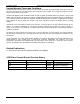
Hewlett-Packard SCSI-Fibre Channel Router Installation and User Guide Appendix A: SCSI-Fibre Channel Router Specifications Applications Provides connectivity between SCSI High Voltage Differential (HVD) and Fibre Channel equipment and vice versa. Hardware Features SCSI Connectivity • • • • • Protocol: Data Transfer Rate: SCSI-2: Device Support: Supports: SCSI-2 Ultra-Wide Differential (40MB/sec); supports either initiator (host) or target (device) protocol.
Hewlett-Packard SCSI-Fibre Channel Router Installation and User Guide Appendix B: Diagnostic Status Codes User Serviceable Diagnostic Status Codes Status Code Description 006 Too many SCSI errors recorded. 058 The SCSI-FC Router detected a FC Unique ID duplication in the same loop. The SCSI-FC Router has completed clearing the Node Mapping Table. An illegal host mode has been used. 060 068 Action Check all connections and/or replace the SCSI cables with "known-good" shielded SCSI cables.
Hewlett-Packard SCSI-Fibre Channel Router Installation and User Guide Index switch two (SW2) ........................................................ 10 C Cables and Connections check ........................................................................... 20 Cabling optical.......................................................................... 19 SCSI ............................................................................ 19 Clean Up Configuration Table...................................