Installation Guide XX268-00-00 CE102D Network Indoor Camera Dome Vicon Industries Inc. Tel: 631-952-2288 Fax: 631-951-2288 Toll Free: 800-645-9116 24-Hour Technical Support: 800-34-VICON (800-348-4266) UK: 44/(0) 1489-566300 Vicon Industries Inc. does not warrant that the functions contained in this equipment will meet your requirements or that the operation will be entirely error free or perform precisely as described in the documentation.
WARNING TO REDUCE THE RISK OF FIRE OR ELECTRIC SHOCK, DO NOT INSERT ANY METALLIC OBJECT THROUGH THE VENTILATION GRILLS OR OTHER OPENINGS ON THE EQUIPMENT. CAUTION EXPLANATION OF GRAPHICAL SYMBOLS The lightning flash with arrowhead symbol, within an equilateral triangle, is intended to alert the user to the presence of uninsulated "dangerous voltage" within the product’s enclosure that may be of sufficient magnitude to constitute a risk of electric shock.
FCC COMPLIANCE STATEMENT INFORMATION TO THE USER: THIS EQUIPMENT HAS BEEN TESTED AND FOUND TO COMPLY WITH THE LIMITS FOR A CLASS A DIGITAL DEVICE, PURSUANT TO PART 15 OF THE FCC RULES. THESE LIMITS ARE DESIGNED TO PROVIDE REASONABLE PROTECTION AGAINST HARMFUL INTERFERENCE WHEN THE EQUIPMENT IS OPERATED IN A COMMERCIAL ENVIRONMENT.
IMPORTANT SAFETY INSTRUCTIONS 1. 2. 3. 4. 5. 6. 7. 8. 9. 10. 11. 12. 13. 14. Read these instructions. Keep these instructions. Heed all warnings. Follow all instructions. Do not use this apparatus near water. Clean only with dry cloth. Do not block any ventilation openings. Install in accordance with the manufacturer’s instructions. Do not install near any heat sources such as radiators, heat registers, stoves, or other apparatus (including amplifiers) that produce heat.
Contents 1. Description ------------------------------------------------------------------6 1.1 Components - ------------------------------------------------------------------------------------------ 6 1.2 Key Features - ------------------------------------------------------------------------------------------ 7 2. Installation ------------------------------------------------------------------ 8 2.
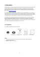
1. Description The information in this manual provides quick installation and setup procedures for the CE102D Series of Camera Domes. These units should only be installed by a qualified technician using approved materials in conformance with federal, state, and local codes. Read these instructions thoroughly before beginning an installation. Always refer to Vicon’s website to assure you have the most up-todate manual, www.vicon-security.com.
1.2 Key Features • Brilliant video quality The network camera offers the highly efficient H.264 video compression, which drastically reduces bandwidth and storage requirements without compromising image quality. Motion JPEG is also supported for increased flexibility. • Triple streams The network camera can deliver triple video streams simultaneously at full frame rate in all resolutions up to 1920 x 1080 using Motion JPEG and H.264 (or MPEG-4).
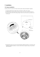
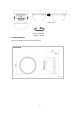
2. Installation 2.1 Camera Installation Carefully remove the contents from the box and verity that nothing was damaged in shipment. 1) Using the template sheet provided, make screw holes for camera on the ceiling. 2) Disassemble the camera by gently turning the camera cover counter-clockwise to remove it. 3) Secure the dome camera to the ceiling using the anchors (2x) and screws (2x) provided in the accessory kit. 4) Reassemble the dome cover to the camera assembly by aligning the notches.
Locking Screw Camera Dimension Refer to the diagrams below for exact dimensions.
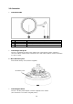
2.2 Connection • Connection Cable NO 1 2 3 • Name Lens Power Cable Ethernet Cable Description Allows wide area to be monitored Cable for power source (12 VDC ) Cable for Ethernet (PoE) Connecting to the RJ-45 Connect a standard RJ-45 cable to the network port of the network camera. Generally a cross-over cable is used for direct connection to PC, while a direct cable is used for connection to a hub or switch. Micro SD memory slot Insert the SD memory card (customer supplied).
2.3 Network Connection and IP assignment The network camera is designed for use on an Ethernet network and requires an IP address for access. Most networks today have a DHCP server that automatically assigns IP addresses to connected devices. By factory default, your camera is set to obtain the IP address automatically via DHCP server. If your network does not have a DHCP server the network camera will use 192.168.1.100 as the default IP address.
3. Operation The network camera can be used with Windows® operating system and browsers. The recommended browsers are Internet Explorer®, Safari®, Firefox®, Opera® and Google® Chrome® with Windows. Note: To view streaming video in Microsoft® Internet Explorer, set your browser to allow ActiveX controls. Note: Some screens may appear different (i.e., color scheme) depending on the firmware version, but the functionality is the same or similar. 3.1 Access from a browser 1. 2. 3. Start a browser (i.e.
3.2. Access from the internet Once connected, the network camera is accessible on your local network (LAN). To access the network camera from the Internet you must configure your broadband router to allow incoming data traffic to the network camera. To do this, enable the NAT-traversal feature, which will attempt to automatically configure the router to allow access to the network camera. This is enabled from Setup > System > Network > NAT. For more information, refer to “3.5.
1) General controls Live View Page Search & Playback Page Setup Page Help Page The video drop-down list allows you to select a customized or pre-programmed video stream on the live view page. Stream profiles are configured under Setup > Basic Configuration > Video & Image. For more information, see section “3.5.1 Basic Configuration > Video & Image” of this user’s manual. The resolution drop-down list allows the selection of the most suitable video resolution to be displayed on Live View page.
3.5 Network Camera Setup This section describes how to configure the network camera, and is intended for product Administrators, who have unrestricted access to all the Setup tools, and Operators, who have access to the settings for Basic, Live View, Video & Image and System Configuration. The network camera is configured by clicking Setup in the top right-hand corner of the Live View page. Click on to access the online help that explains the setup tools.
1) Users User access control is enabled by default. An administrator can set up other users, by giving these user names and passwords. It is also possible to allow anonymous viewer login, which means that anybody may access the Live View page, as described below: The user list displays the authorized users and user groups (levels): User Group Guest Operator Administrator Authority Provides the lowest level of access, which only allows access to the Live View page.
2) Network The network camera supports both IP version 4 and IP version 6. Both versions may be enabled simultaneously, and at least one version must always be enabled. When using IPv4, the IP address for the network camera can be set automatically via DHCP, or a static IP address can be set manually. If IPv6 is enabled, the network camera receives an IP address according to the configuration in the network router. There is also the option of using the Internet Dynamic DNS Service.
3) Video & Image • Stream1 Setting Codec: The codec settings are separated into MPEG4 and H.264. H.264 is also known as MPEG-4 Part 10. This is the new generation compression standard for digital video. This function offers higher video resolution than Motion JPEG or MPEG-4 at the same bit rate and bandwidth, or the same quality video at a lower bit rate. There are 4 pre-programmed stream profiles available for quick set-up.
* MPEG4 SP (Simple Profile): Mostly aimed for use in situations where low bit rate and low resolution are mandated by other conditions of the applications, like network bandwidth, device size, etc. - Resolution: Resolution enables users to determine a basic screen size when having access through the Web Browser or PC program. The screen size control comes in several modes, such as 1920x1080, 1280x1024, 1280x720, 800x600, 704x480 (576), 640x480, 352x240 (288) and 320x240.
• Stream2 Setting Sometimes the image size is large due to low light or complex scenery. Adjusting the frame rate and quality helps to control the bandwidth and storage used by the Motion JPEG video stream in these situations. Limiting the frame rate and quality optimizes bandwidth and storage usage, but may give poor image quality. To prevent increased bandwidth and storage usage, the Resolution, Frame rate, and Frame Quality should be set to an optimal value.
• • New Server Time Select your time zone from the drop-down list. If you want the server clock to automatically adjust for daylight savings time, select the “Automatically adjusts for daylight saving time changes”. From the Time Mode section, select the preferred method to use for setting the time: Synchronize with computer time: Sets the time from the clock on your computer. Synchronize with NTP Server: The network camera will obtain the time from an NTP server every 60 minutes.
3.5.3 Video & Image Basic Refer to “3.5.1 Basic Configuration > Video & Image” for more details.
Image • Image Appearance This page provides access to the advanced image settings for the network camera. - Brightness: The image brightness can be adjusted in the range 1-10, where a higher value produces a brighter image. Contrast: Adjust the image's contrast by raising or lowering the value in this field, 1-10. Saturation: Select an appropriate level by entering a value in the range 1-10. Lower values mean less color saturation. Hue: Select an appropriate level by entering a value in the range 1-10.
AE & AWB • Exposure control This page provides access to the advanced exposure control settings for the network camera. * * * * * Mode: Supports exposure modes to control the amount of light detected by the camera sensor based on settings for light conditions. The default setting is Auto mode. Automatic: Automatically sets the amount of light detected by the image sensor. Hold Current: Fixes the exposure at its current state. Value: Select a value in the drop-down list to tune the exposure.
• White Balance Control This adjusts the relative amount of red, green and blue primary colors in the image so that the neutral colors are reproduced correctly. The camera can be set to automatically adjust for the type of light and compensate for its color. Alternatively, the type of light source can be set manually. From the drop-down list, select the white balance setting suitable for the lighting used for your camera.
• Day & Night Control * * * - • Mode: Select the day/night mode from among three modes. Automatic: Normally works in day mode; switches automatically to night mode in a dark place. Day: Always works in day mode. Night: Always works in night mode. Threshold: Controls the how fast the change is from day to night or night to day. *High: Quickly changes to day mode, but slowly changes to night mode. *Low: Quickly changes to night mode, but slowly changes to day mode.
The privacy masks are configured by Mask windows. Each window can be selected by clicking with the mouse. It is also possible to resize, delete or move the window, by selecting the appropriate window at the mouse menu on the video screen. To create a mask window, follow steps: 1. Click the right button of mouse to see the mouse menu. 2. Select New Privacy Mask in the mouse menu. 3. Click and drag mouse to designate a mask window area. A mask window name can also be modified or deleted.
3.5.4 Event 1) Event-In On Boot This is used to trigger the event every time the network camera is started. Select “Enable on boot” to activate the motion event. Enter the Dwell time the event lasts from the point of detection, 1-180 seconds. When the settings are complete, click Save, or click Reset to revert to previously saved settings.
Manual Trigger This option makes use of the manual trigger button provided on the Live View page, which is used to start or stop the event type manually. Alternatively, the event can be triggered via the product's API (Application Programming Interface). Select “Enable manual trigger” to activate the manual trigger (for up to 4 manual triggers). Set the dwell time the trigger lasts. When the settings are complete, click Save, or click Reset to revert to previously saved settings.
Motion Motion detection is used to generate an alarm whenever movement occurs (or stops) in the video image. A total of 8 Motion and/or Mask windows can be created and configured. Motion is detected in defined Motion windows, which are placed in the video image to target specific areas. Movement in the areas outside the motion windows will be ignored. If part of a motion window needs to be masked, this can be configured in a Mask window.
To create a motion or mask window, follow steps: 1. Click the right button of mouse to see the mouse menu. 2. Select New Motion (or Mask) Window in the mouse menu. 3. Click and drag mouse to designate a motion area. • Motion Detection Setting The behavior for each window is defined by adjusting the Threshold and Sensitivity, as described below. The combination of these parameters defines whether motion has occurred; motion detection frequency is increased with a high sensitivity and a low threshold.
Network Loss This is used to trigger the event every time the network connection is failed. Select “Enable network loss” to activate the Network Loss event. Select a dwell time for how long the event will last from the point of detection. When the settings are complete, click Save, or click Reset to revert to previously saved settings.
2) Event-Out SMTP (E-Mail) The network camera can be configured to send event and error email messages via SMTP (Simple Mail Transfer Protocol). Select “Enable SMTP” to activate the SMTP operation. Sender: Enter the email address to be used as the sender for all messages sent by the network camera. Interval: Represents the frequency of the email notification when an event occurs. Aggregate events: Shows the maximum number of emails sent within each interval.
SMTP authentication, you must define the weakest authentication method allowed. Login Method: Set the weakest method allowed to the highest/safest method supported by the mail server. The most secure method is listed in the drop-down list: Login/Plain • SMTP (E-Mail) Receiver Receiver: Enter an email address for a receiver. You can register up to 8 e-mail addresses of recipients.
- • Remote directory: Specify the path to the directory where the uploaded images will be stored. If this directory does not already exist on the FTP server, there will be an error message when uploading. User name/Password: Provide your log-in information. JPEG Setting Pre-event: A pre-event buffer contains images from the time immediately preceding the event trigger. These are stored internally in the server. This buffer can be very useful when checking to see what happened to cause the event trigger.
When the setup is complete, the connection can be tested by clicking the Test button. ▼ Record When the network camera detects an event, it can record video stream in the Micro SD Memory (not supplied) or NAS (Network Attached Device) as a storage device. C Check the "Enable Record" box to enable the service. • Record Setting Overwrite: Click checkbox to overwrite the storage device. Stream Type: You can select Stream 1, Stream 2, or Stream 3. * Stream1: H.
• Record Schedule The weekly recording schedule can be set for each day. Drag or click a box area; clicking the block toggles the recording between on and off. Click the “All Select” button to set a schedule for the entire week, 24/7; to record for a whole day, click in the “0” box and drag to “23.” Note that the time is in 24 hour format, where 0 indicates midnight. • Device Setting Select Device Type to be recorded in the drop-down list. The screen changes according to selection.
▼ Event Notification When the network camera detects an event, it can send a message to a designated server that this event has occurred. Check the "Enable event notification" box to enable the service. Enter the notification server URL and port.
The event map allows you to change the settings and establish a schedule for each event trigger from the network camera; up to a max. 15 events can be registered. Click the Add button to make a new event map; a popup window displays as below. To change an existing event, select that event and click the Modify button; this same window will display and the information can be changed as required. Selecting an event and clicking Remove deletes the event. • General Enter the name for a new event map.
3.5.5 System 1) Information You can enter the system information. This page is very useful as a reference for information after installation. • Device Name Configuration Enter the device name. • Location Configuration Enter the location information. You can enter up to four locations. When the settings are complete, click Save, or click Reset to revert to previously saved settings.
2) Security Users User access control is enabled by default, when the administrator sets the root password on first access. New users are authorized with user names and passwords, or the administrator can choose to allow anonymous viewer login to the Live View page, as described below: • User Setting Check the box to "Enable anonymous viewer login" to the network camera without a user account. When using the user account, users have to log-in at every access.
HTTPS For greater security, the network camera can be configured to use HTTPS [Hypertext Transfer Protocol over SSL (Secure Socket Layer)], so that all communication that would otherwise go via HTTP will instead go via an encrypted HTTPS connection. • HTTPS Connection Policy Choose the form of connection you wish to use from the drop-down list for the administrator, Operator and Viewer to enable HTTPS connection (set to HTTP by default).
IP Filtering Checking the "Enable IP address filtering" box enables the IP address filtering function. When the IP address filter is enabled, addresses added to the list are set as allowed or denied addresses. All other IP addresses not in this list will then be allowed or denied access accordingly, that is, if the addresses in the list are allowed, then all others are denied access, and vice versa.
OpenVPN OpenVPN is an open source software application that implements virtual private network (VPN) techniques for creating secure point-to-point or site-to-site connections in routed or bridged configurations and remote access facilities. OpenVPN can run over User Datagram Protocol (UDP) or Transmission Control Protocol (TCP) transports; multiplexing is created SSL tunnels on a single TCP/UDP port. OpenVPN uses the OpenSSL library to provide encryption of both the data and control channels.
• Server Mode Configuration Protocol type: Choose Protocol type, either UDP and TCP; UDP is preferred. Port: Type in Port number to use, default is 1194. Use LZO compression: Determines whether or not to use cypher compression in connection. Export CA certificate: Download the CA certificate issued by Server for Client setup. After finishing setup, click Save button; the camera now operates as an OpenVPN Server.
3) Date & Time • Current Server Time This displays the current date and time (24h clock). The time can be displayed in 12h clock format (see below). • New Server Time Select your time zone from the drop-down list. If you want the server clock to automatically adjust for daylight savings time, select “Automatically adjusts for daylight saving time changes”.
4) Network Setting in regard to network can be executed. Settings for IP, DNS, Host Name, Port, and ARP/Ping can be established, along with setting for DDNS, uPnP, QoS, Zeroconfig and Bonjour. Basic • IP Address Configuration: Obtain IP address via DHCP: Dynamic Host Configuration Protocol (DHCP) is a protocol that lets network administrators centrally manage and automate the assignment of IP addresses on a network. DHCP is enabled by default.
* • Default router: Specify the IP address of the default router (gateway) used for connecting devices attached to different networks and network segments. IPv6 Address Configuration Check this box to enable IPv6. Other settings for IPv6 are configured in the network router. • DNS Configuration DNS (Domain Name Service) provides the translation of host names to IP addresses on your network. Check the radio button to obtain DNS server via DHCP or set the DNS server.
DDNS • Internet DDNS (Dynamic Domain Name Service) When using the high-speed Internet with the telephone or cable network, users can operate the Network Camera even on the floating IP environment in which IPs are changed at every access. Users should receive an account and password by visiting a DDNS service like http://www.dyndns.com/, * * * * * * * Enable DDNS: Check to get DDNS service to be available. DDNS Server: Select the DDNS server. Registered host: Enter an address of the DDNS server.
RTP Create a setting for sending and receiving video on a real-time basis. These settings are the IP address, port number, and Time-To-Live value (TTL) to use for the media stream(s) in multicast H.264 format. Only certain IP addresses and port numbers should be used for multicast streams. • Port Range Start/End port: Enter a value between 30000 and 39920 • Multicast This function is for sending video to multicast group. Enable Multicast: Check the checkbox to enable multicast operation.
UPnP The network camera includes support for UPnP™. UPnP is enabled by default, so the network camera is automatically detected by operating systems and clients that support this protocol. Enter a name in the Friendly name field. Note: UPnP must be installed on your workstation if running Windows XP. To do this, open the Control Panel from the Start Menu and select Add/Remove Programs. Select Add/Remove Windows Components and open the Networking Services section.
• DSCP Settings For each type of network traffic supported by your network video product, enter a DSCP (Differentiated Services Code Point) value. This value is used to mark the traffic’s IP header. When the marked traffic reaches a network router or switch, the DSCP value in the IP header tells the router or switch which type of treatment to apply to this type of traffic, for example, how much bandwidth to reserve for it.
NAT A broadband router allows devices on a private network (LAN) to share a single connection to the Internet. This is done by forwarding network traffic from the private network to the “outside”, that is, the Internet. Security on the private network (LAN) is increased since most broadband routers are pre-configured to stop attempts to access the private network (LAN) from the public network/Internet.
• NAT traversal Settings Enable: Click the Enable button to enable NAT traversal; pressing the button toggles between enable and disable. When enabled, the network camera attempts to configure port mapping in a NAT router on your network, using UPnP. Note that UPnP must be enabled in the network camera (see System>Network>UPnP). Enter a NAT router and enter the external port number for the router in the field provided.
Zero configuration networking allows devices such as computers and printers to connect to a network automatically. Without zeroconf, a network administrator must set up services, such as Dynamic Host Configuration Protocol (DHCP) and Domain Name System (DNS), or configure each computer's network settings manually, which may be difficult and time-consuming.
5) Language Select a user language. The language choices are English, Russian, Korean and Chinese.
6) Maintenance • Maintenance Restart: The unit is restarted without changing any of the settings. Use this method if the unit is not behaving as expected. Reset: The unit is restarted and most current settings are reset to factory default values. The settings that are not affected are: * the boot protocol (DHCP or static) * the static IP address * the default router * the subnet mask * the system time Default: The default button should be used with caution.
• Backup Click the Backup button to save setting values that users enter to the network camera to a user PC. • Restore Click the Restore button to import and apply setting values saved to a user PC. Note: Backup and Restore can only be used on the same unit running the same firmware. This feature is not intended for multi-configurations or for firmware upgrades. 7) Support The support page provides valuable information on troubleshooting and contact information, should you require technical assistance.
• Health Check - System Check: Click the System Check button to get the important information about the camera’s system resources. The pop-up window displays as below. - Media Check: Click the Media Check button to get the information about the camera’s video stream. The pop-up window displays as below.
- Networks Check: Click the Network Check button to get the information about the camera’s network setting and traffic. The pop-up window displays as below. - Hardware Check: Click the Hardware Check button to diagnose the camera’s hardware, such as video.
3.6 Playback The Playback window contains a list of recordings made to the memory card. It shows each recording's start time, length, the event type used to start the recording, calendar and time slice bar indicates if the recording exists or not. The description of playback window follows.
Zoom In: zoom in the video clip Full Screen: display full screen of the video. (3) Time Chart Display an hour-based search screen for the chosen date. If there is recording data, a blue section will be displayed on a 24-hour basis. If you select a particular hour in the chart, a yellow square on the hour will be displayed. (4) Search Calendar Search results from the SD local storage in the network camera connected are displayed monthly.
3.7 Help The Help information window will be provided as a popup window so that users can open and read it without a need for log-in. It will offer a description on setting and Help page by which users can manipulate the network camera without a reference to the manual.
3.8 Resetting to the factory default settings To reset the network camera to the original factory settings, go to the Setup>System> Maintenance web page (described in “3.5.5 System > Maintenance”) or use the Reset button on the network camera, as described below. Reset Button • Using the Reset Button Follow the instructions below to reset the network camera to the factory default settings using the Reset button. 1. 2. 3. 4. 5. 6. 7. Power off the network camera by disconnecting the power adapter.
4. Appendix 4.1 Troubleshooting Troubleshooting if problems occur, verify the installation of the network camera with the instructions in this manual and with other operating equipment. Isolate the problem to the specific piece of equipment in the system and refer to the equipment manual for further information. Problems/Symptoms The camera cannot be accessed by some clients. The camera works locally, but not externally. Poor or intermittent network connection.
4.2 Preventive Maintenance Preventive maintenance allows detection and correction of minor that faults before they become serious and cause equipment failure. Every three-month, perform the following maintenance. 1. 2. 3. Inspect all connection cables for deterioration or other damage. Clean components with a clean damp cloth. Verify that all the mounting hardware is secure.
4.3 Product Specification Main Item C A M E R A Image sensor Active Array Lens Angle of View 90.0°(H) x 50.0(V) IR Distance Min. illumination Shutter Speed 65 ft (20m) (with built-in 24 IR LEDs) Color: 0.2Lux, B/W: 0.0Lux (F1.8, 50IRE with IR On) 1/20,000 ~ 1/30 (Slow shutter 1/15, 1/8 and 1/4) -. Motion JPEG -. MPEG-4 Part2 -. H.264 (MPEG-4 Part 10) -. Profiles: H.264 HP, MP, and BP, MPEG-4 SP Simultaneously H.264(or MPEG-4) and MJPEG Controllable Frame Rate and Bandwidth VBR/CBR H.
System Requirement for Web Browser Operating System: Microsoft® Windows® OS Series CPU: Intel® Core 2 Duo 2GHz or higher, 1GB RAM or more, 10GB free disk or higher VGA: AGP, Video RAM 32MB or higher (1024x768, 24bpp or higher) General performance considerations When setting up your system, it is important to consider how various settings and situations will affect performance. Some factors affect the amount of bandwidth (the bitrate) required, others can affect the frame rate, and some affect both.
Shipping Instructions Use the following procedure when returning a unit to the factory: 1. Call or write Vicon f or a Return A uthorization ( R.A.) at one of t he locations listed be low. Record the name of the Vicon employee who issued the R.A. Vicon Industries Inc. 131 Heartland Boulevard Edgewood, NY 11717 Phone: 631-952-2288; Toll-Free: 1-800-645-9116; Fax: 631-951-2288 For service or returns from countries in Europe, contact: Vicon Industries (U.K.
Vicon Standard Equipment Warranty Vicon Industries I nc. ( the “ Company”) w arrants y our equ ipment t o b e f ree f rom defects i n material and workmanship under Normal Use from the date of original retail purchase for a period of three years, with the following exceptions: 1. 2. 3. 4. 5. 6. 7. 8. Monitors, all models: One year from date of original retail purchase. Uninterruptible Power Supplies: Two years from date of original retail purchase.
Vicon Industries Inc. Internet Address: www.vicon-security.