Quick Guide XX269-10-00 CE202D-WN Network Outdoor Camera Dome Vicon Industries Inc. Tel: 631-952-2288 Fax: 631-951-2288 Toll Free: 800-645-9116 24-Hour Technical Support: 800-34-VICON (800-348-4266) UK: 44/(0) 1489-566300 Vicon Industries Inc. does not warrant that the functions contained in this equipment will meet your requirements or that the operation will be entirely error free or perform precisely as described in the documentation.
1. Description The information in this manual provides quick installation and setup procedures for the CE202D-WN Camera Dome. These units should only be installed by a qualified technician using approved materials in conformance with federal, state, and local codes. Read these instructions thoroughly before beginning an installation. Always refer to Vicon’s website to assure you have the most up-to-date manual, www.vicon-security.com. The CE202D-WN is designed for demanding outdoor security installations.
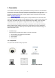
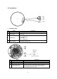
Note 1: Check your package to make sure that you received the complete system, including all components shown above. Note 2: Adapter for 12 VDC is not supplied; the optional V920D-OSD Controller can be purchased separately.. • Contents in the installation CD 1. 2. The CE202D-WN User’s Manual The SmartManager User’s Manual 3.
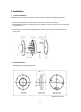
2. Installation • Camera Installation Carefully remove the contents from the box, and verity that nothing was damaged in shipment. 1) Using the template sheet provided, make screw holes for camera on the ceiling. 2) Disassemble the camera by loosening the four (4) captive screws securing the cover and removing the camera cover. 3) Secure the dome camera to the ceiling using the anchors (2x) and screws (2x) provided in the accessory kit. Camera Dimension The diagram below provides dimensions.
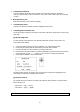
2.2 Connections NO 1 Connection Cable Name Audio Cable 2 Power Cable 3 ALARM Cable 4 Ethernet Cable NO 1 2 3 4 Description Audio line output, RCA Jack Red: 12 VDC White: GND Blue: GND Gray: ALARM INPUT Brown: GND Yellow : ALARM OUT Ethernet, RJ-45 port compatible with 10/100Mbps having PoE functionality. Modular Jack Name Micro-SD Slot Factory Default Button Mic Port Service Monitor Port Description Micro-SD memory slot Button for the factory default setting Microphone input.
• • Connecting to the RJ-45 Connect a standard RJ-45 cable to the network port of the network camera. Generally a cross-over cable is used for direct connection to a PC, while a direct cable is used for connection to a hub. Micro SD memory slot Insert the SD memory card (customer supplied). Connecting the Power Connect a 12 VDC power adaptor (customer supplied) to the camera.
2.3 Network Connection and IP assignment The network camera is designed for use on an Ethernet network and requires an IP address for access. Most networks today have a DHCP server that automatically assigns IP addresses to connected devices. By the factory default, your camera is set to obtain the IP address automatically via DHCP server. If your network does not have a DHCP server the network camera will use 192.168.1.100 as the default IP address.
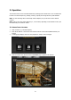
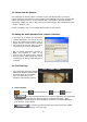
3. Operation The network camera can be used with Windows® operating system and browsers. The recommended browsers are Internet Explorer®, Safari®, Firefox®, Opera® and Google Chrome® with Windows. Note: To view streaming video in Microsoft® Internet Explorer, set your browser to allow ActiveX controls. Note: Some screens may appear different (i.e., color scheme) depending on the firmware version, but the functionality is the same or similar. 3.1 Access from a browser 1. 2. 3. Start a browser (i.e.
3.2. Access from the internet Once connected, the network camera is accessible on your local network (LAN). To access the network camera from the Internet you must configure your broadband router to allow incoming data traffic to the network camera. To do this, enable the NAT-traversal feature, which will attempt to automatically configure the router to allow access to the network camera. This is enabled from Setup > System > Network > NAT. For more information, refer to “3.5.
The protocol drop-down list allows the selection of the combination of protocols and methods to use depending on your viewing requirements and on the properties of the network. 2) Control toolbar The live viewer toolbar is available on the web browser page only. It displays the following buttons: The Stop button stops the video stream being played. Pressing the key again toggles the start and stop. The Start button connects to the network camera to start playing a video stream.
• Adjusting Pan and Tilt: Click the navigation button in the PT control panel. Pan Control: ►(Right), ◄(Left) Tilt Control: ▲(Up), ▼(Down) 3.5 Network Camera Setup This section describes how to configure the network camera and is intended for product Administrators, who have unrestricted access to all the Setup tools, and Operators, who have access to the settings for Basic, Live View, Video & Image and System Configuration.
3.6 Resetting to the factory default settings To reset the network camera to the original factory settings, go to the Setup>System> Maintenance web page (described in “3.5.6 System > Maintenance”) or use the Reset button on the network camera, as described below. • Using the Reset Button Follow the instructions below to reset the Network Camera to the factory default settings using the Reset button. 1. 2. 2. 3. 4. 5. 6. Power off the network camera by disconnecting the power adapter.
Vicon Industries Inc. Internet Address: www.vicon-security.com SN663V IP Camera Dome Rev.