Quick Guide XX249-41-00 Cruiser™ SN663V-A Outdoor PTZ Network Camera Dome Vicon Industries Inc. Tel: 631-952-2288 Fax: 631-951-2288 Toll Free: 800-645-9116 24-Hour Technical Support: 800-34-VICON (800-348-4266) UK: 44/(0) 1489-566300 Vicon Industries Inc. does not warrant that the functions contained in this equipment will meet your requirements or that the operation will be entirely error free or perform precisely as described in the documentation.
1 Introduction The SN663V-A network camera is an outdoor PTZ camera dome that includes a 1080p high resolution camera lens combination that provides video transmission over a network. It is fully featured for security surveillance and remote monitoring needs. The network camera supports H.264 compression technology as well as M-JPEG compression.
1.2 Key Features • Brilliant video quality The network camera offers the highly efficient H.264 video compression, which drastically reduces bandwidth and storage requirements without compromising image quality. Motion JPEG is also supported for increased flexibility. • Dual or Triple Streams The network camera can deliver dual or triple video streams simultaneously at full frame rate in all resolutions up to Full-HD (1920 x 1080p) using Motion H.264 and JPEG.
2 Installation 2.1 Installation The dome camera is for use in surface or pendant mounting applications, and the mounting member must be capable of supporting loads of up to 10 lb (4.5 kg). (Pendant mounting must use pendant mount accessory.) The dome cameras mounting bracket should be attached to a structural object, such as hard wood, wall stud or ceiling rafter that supports the weight of the dome camera. CAUTION: A silicone rubber sealant must be applied to seal the housing to secure waterproofing.
CAUTION: Before installing mounting bracket to surface pre-adjust the four mounting screws ”A” on the base of the dome camera to best match the mounting bracket locked position. Unscrew the locking screw on the side of the dome’s base and fit the tab of the mounting bracket into the locking slot. Screws ”A” should not be too tight or too loose when the dome is in the locked position. After setting the proper positions of screws ”A” remove the mounting bracket and install it to the proper surface.
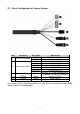
2.2 Basic Configuration of Camera System No. Connector Wire Color RED WHITE PINK GRAY GREEN BLUE BROWN YELLOW 1 3-pin terminal block 2 6-pin terminal block 3 RJ-45 BLACK 4 5 STEREO STEREO GRAY BLACK Description 24VAC or 12VDC+ 24VAC or 12VDCALARM INPUT 1 ALARM INPUT 2 ALARM INPUT 3 ALARM INPUT 4 GND ALARM OUTPUT Ethernet, RJ-45 port compatible with 10/100Mbps having PoE functionality.
2.3 Micro-SD Card Insertion User can install and change Micro-SD card as shown in the following picture. 1. Open the Micro-SD card cover. 2. Install or change Micro-SD card. 3. Tightly close the Micro-SD card cover to ensure waterproofness.
2.4 Connections • Connecting the Network Connect a standard RJ-45 cable to the network port of the camera. Generally a crossover cable is used for directly connection to PC, while a direct cable is used for connection to a hub. • Connecting Alarms – A1,A2,A3,A4 (Alarm Input 1,2,3,4) You can use external devices to signal the camera to react on events. Mechanical or electrical switches can be wired to the A1,A2,A3,A4 (Alarm Input 1,2,3,4) and G (Ground) connectors.
2.4.1 Network Connection & IP assignment The network camera is designed for use on an Ethernet network and requires an IP address for access. Most networks today have a DHCP server that automatically assigns IP addresses to connected devices. By the factory default, your camera is set to obtain the IP address automatically via DHCP server. If your network does not have a DHCP server the network camera will use 192.168.1.100 as the default IP address.
3 Operation The network camera can be used with Windows operating system and browsers. The recommended browsers are Internet Explorer, Safari, Firefox, Opera and Google Chrome with Windows. NOTE: To view streaming video in Microsoft Internet Explorer, set your browser to allow ActiveX controls. 3.1 Access from a browser 1. Start a browser (Internet Explorer). 2. Enter the IP address or host name of the network camera in the Location/Address field of your browser. 3. You can see a starting page.
3.2 Access from the internet Once connected, the network camera is accessible on your local network (LAN). To access the network camera from the Internet you must configure your broadband router to allow incoming data traffic to the network camera. To do this, enable the NAT traversal feature, which will attempt to automatically configure the router to allow access to the network camera. This is enabled from Setup > System > Network > NAT.
3.4 Live View Page The Live View page comes in several screen modes: 1920x1080, 1280x1024, 1280x720(960), 1024x768, 704x480(576), 640x480(360) and 320x240. Users are allowed to select the most suitable one out of those modes. Adjust the mode in accordance with your PC specifications and monitoring purposes. 1) General controls Live View Page Playback Page Setup Page Help Page The video drop-down list allows you to select a customized or preprogrammed video stream on the Live View page.
2) Control toolbar The live viewer toolbar is available in the web browser page only. It displays the following buttons: The Stop button stops the video stream being played. Pressing the key again toggles the start and stop. The Start button connects to the network camera or starts playing a video stream. The Pause button pauses the video stream being played. The Snapshot button takes a snapshot of the current image. The location where the image is saved can be specified.
3.5 Playback The Playback window contains a list of recordings made to the memory card. It shows each recording’s start time, length, the event type used to start the recording, calendar and time slice bar indicates if the recording is existed or not. The description of playback window follows. (1) Video Screen You can see the video screen when playing the video clip in the Micro SD memory.
(3) Time Chart Display an hour-based search screen for the chosen date. If there is recording data, a blue section will be displayed on a 24-hour basis. If you select a particular hour in the chart, a yellow square on the hour will be displayed. (4) Speaker Control Bar Use this scale to control the volume of the speakers. (5) Search Calendar Search results from the SD local storage in the network camera connected are displayed monthly.
3.6 Network Camera Setup This section describes how to configure the network camera. Administrator has unrestricted access to all the Setup tools, whereas Operators have access to the settings of Basic Configuration, which are Live View, Video & Image, Audio, Event, Dome Configuration, and System. You can configure the network camera by clicking Setup either in the first connection page or the top second-right button of the Live View page.
Resetting to the factory default settings To reset the network camera to the original factory settings, go to the Setup > System > Maintenance web page (described in ”System > Maintenance” of Users Manual) or use the Reset button on the network camera, as described below: • Using the Reset button: Follow the instructions below to reset the network camera to the factory default settings using the Reset button. 1. Switch off the network camera by disconnecting the power adapter. 2.
System Requirement for Web Browser • Operating System: Microsoft Windows OS Series • CPU: Intel Core 2 Duo 2Ghz or higher, 1GB RAM or more, 10GB free disk or higher • VGA: AGP, Video RAM 32MB or higher (1024x768, 24bpp or higher) General Performance Considerations When setting up your system, it is important to consider how various settings and situations will affect performance. Some factors affect the amount of bandwidth (the bit rate) required, others can affect the frame rate, and some affect both.
Shipping Instructions Use the following procedure when returning a unit to the factory: 1. Call or write Vicon for a Return Authorization (R.A.) at one of the locations listed below. Record the name of the Vicon employee who issued the R.A. Vicon Industries Inc. 135 Fell Court Hauppauge, NY 11788 Phone: 631-952-2288; Toll-Free: 1-800-645-9116; Fax: 631-951-2288 For service or returns from countries in Europe, contact: Vicon Industries (U.K.
Vicon Standard Equipment Warranty Vicon Industries Inc. (the Company) warrants your equipment to be free from defects in material and workmanship under Normal Use from the date of original retail purchase for a period of three years, with the following exceptions: 1. IQEYE Cameras: Two years if purchased before 1/1/2011. 2. IQEYE Cameras: Five years if purchased between 1/2/2011 12/31/2014. 3. Uninterruptible Power Supplies: Two years from date of original retail purchase. 4.
on product(s) purchases from internet auction sites including eBay, uBid or from any other unauthorized resellers. Except as explicitly provided herein, Vicon disclaims all other warranties, including the implied warranties of fitness for a particular purpose and merchantability. Software supplied either separately or in hardware is furnished on an ”As Is” basis. Vicon does not warrant that such software shall be error (bug) free.