
Product specifications


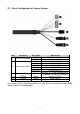


2.2 Basic Configuration of Camera System
No. Connector Wire Color Description
1 3-pin terminal block
RED 24VAC or 12VDC+
WHITE 24VAC or 12VDC-
2 6-pin terminal block
PINK ALARM INPUT 1
GRAY ALARM INPUT 2
GREEN ALARM INPUT 3
BLUE ALARM INPUT 4
BROWN GND
YELLOW ALARM OUTPUT
3 RJ-45 BLACK
Ethernet, RJ-45 port compatible with
10/100Mbps having PoE functionality.
4 STEREO GRAY AUDIO OUTPUT
5 STEREO BLACK AUDIO INPUT
The camera must be installed by qualified service personnel in accordance with all local and
federal electrical and building codes.
7