User Guide XX247-00-05 V-CELL High-Security Corner-Mount Cameras Vicon Industries Inc. Tel: 631-952-2288 Fax: 631-951-2288 Toll Free: 800-645-9116 24-Hour Technical Support: 800-34-VICON (800-348-4266) UK: 44/(0) 1489-566300 Vicon Industries Inc. does not warrant that the functions contained in this equipment will meet your requirements or that the operation will be entirely error free or perform precisely as described in the documentation.
WARNING TO REDUCE THE RISK OF FIRE OR ELECTRIC SHOCK, DO NOT EXPOSE THIS PRODUCT TO RAIN OR MOISTURE. DO NOT INSERT ANY METALLIC OBJECT THROUGH THE VENTILATION GRILLS OR OTHER OPENNINGS ON THE EQUIPMENT. CAUTION EXPLANATION OF GRAPHICAL SYMBOLS The lightning flash with arrowhead symbol, within an equilateral triangle, is intended to alert the user to the presence of uninsulated "dangerous voltage" within the product’s enclosure that may be of sufficient magnitude to constitute a risk of electric shock.
FCC COMPLIANCE STATEMENT INFORMATION TO THE USER: THIS EQUIPMENT HAS BEEN TESTED AND FOUND TO COMPLY WITH THE LIMITS FOR A CLASS A DIGITAL DEVICE, PURSUANT TO PART 15 OF THE FCC RULES. THESE LIMITS ARE DESIGNED TO PROVIDE REASONABLE PROTECTION AGAINST HARMFUL INTERFERENCE WHEN THE EQUIPMENT IS OPERATED IN A COMMERCIAL ENVIRONMENT.
IMPORTANT SAFETY INSTRUCTIONS 1. 2. 3. 4. 5. 6. 7. 8. 9. 10. 11. 12. 13. 14. Read these instructions. Keep these instructions. Heed all warnings. Follow all instructions. Do not use this apparatus near water. Clean only with dry cloth. Do not block any ventilation openings. Install in accordance with the manufacturer’s instructions. Do not install near any heat sources such as radiators, heat registers, stoves, or other apparatus (including amplifiers) that produce heat.
Contents 1. Description ------------------------------------------------------------------6 1.1 Components -- ------------------------------------------------------------------------------------------- 6 1.2 Key Features - ------------------------------------------------------------------------------------------- 7 2. Installation ------------------------------------------------------------------- 8 2.1 2.2 2.3 2.4 2.
1. Description The information in this manual provides quick installation and setup procedures for the V-CELL series of High-Security Corner-Mounted Cameras. These units should only be installed by a qualified technician using approved materials in conformance with federal, state, and local codes. Read these instructions thoroughly before beginning an installation. Refer to the complete manual for detailed information.
1.2 V-CELL-IP Key Features • Brilliant video quality The Network Camera offers the highly efficient H.264 video compression, which drastically reduces bandwidth and storage requirements without compromising image quality. Motion JPEG is also supported for increased flexibility. • Dual or Triple streams The Network Camera can deliver dual or triple video streams simultaneously at full frame rate in all resolutions up to 4CIF(704x480 or 704x576) using Motion JPEG and H.264 (or MPEG-4).
2. Installation 2.
2.2 Quick Installation Below is an overview for installing the V-CELL camera. When using rear cover, refer to the diagram that follows. Detailed instructions follow. 1. Use camera mounting frame as template to mark mounting holes on mounting surface. (Fig.1) 2. Drill holes for mounting base and a minimum 3/4 in. hole for routing wines. (Fig.1) 3. Mount camera mounting frame using appropriate hardware for mounting surface. (Fig.2) 4. Route wires through hole in wall and out through base plate. (Fig.2). 5.
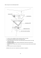
When using rear cover, follow diagram below. 1. Use rear cover as template to mark mounting and cable access holes. 2. Drill mounting and cable access holes in mounting surface. 3. Insert cable clamp into access hole, route cables through clamp and mount cover using appropriate hardware. 4. Use camera mounting frame to mark its mounting holes, drill holes and mount using appropriate hardware. 5. Terminate wires to camera board. Feed the excess wire back through cable clamp and tighten clamp. 6.
- IP Camera - Analog Camera 11
- IP Camera - Analog Camera 12
2.3 Unpacking and Inspection All Vicon equipment is inspected and tested before leaving the factory. It is the carrier’s responsibility to deliver the equipment in the same condition in which it left the factory. Inspection for Visible Damage Immediately inspect the cartons upon delivery. On all copies of the carrier’s freight bill, make a note of any visible damage. Make sure the carrier’s agent (the person making the delivery) signs the note on all copies of the bill.
interior of the housing is required later. Additionally, a rear cover is supplied for those installations requiring Canadian UL compliance or extra protection from fire. Installation without the rear cover: 1. Remove the front plate using the no. 20 Torx bit provided; retain the screws in a safe place. Using the camera mounting frame as a template, mark the locations of the mounting holes on the three mounting tabs (2 holes per tab).
Cable Connections All cabling is done to the boards located on the back of the front plate. Note: Vicon systems and components, like most electronic equipment, require a clean, stable power source. Voltage irregularities such as surges, drops, and interruptions can affect the operation of your equipment and, in severe cases, damage certain components. 8-pin terminal block on board. Pinouts are as follows (printed on the board): Pin1 : AUDIO OUT Pin 2 : GND Pin.3 : AUDIO IN Pin4 : GND Pin.
OSD Menu for Analog Camera Settings can be made using the contact switch on the plug in controller. CAMERA OPERATION WITH OSD EXPOSURE SET COLOR SET DAY & NIGHT SET SPECIAL SET MOTION DET. PRIVACY SET SETUP EXIT < COLOR > LENS WB MODE E. SHUTTER R-Y GAIN BLC B-Y GAIN HDR RETURN AGC SENSE UP RETURN D/N MODE C-SUP A-SUP RETURN MIRROR SHARPNESS GAMMA FREEZE NEGA 3D DNR D_ZOOM SLC ECLIPSE DIS RETURN < MOTION DET.
OSD MAIN SCREEN All OSD operation is via the contact switch on the plug in controller. [CENTER] Turn OSD menu ON or to go into Sub Menu [UP] / [DOWN] UP or DOWN of Cursor [LEFT] / [RIGHT] Change setting Press the [ENTER] button to access the “EXPOSURE SET” mode. 1) LENS: Select the type of lens. (This camera has a fixed lens.) MANUAL: Select when fixed lens is used. Sub Menu - MANUAL Level adjustment (Adjust brightness of fixed lens.) DC: Select when DC Varifocal lens is used.
Press the [ENTER] button to access the “COLOR SET” mode 1) WB MODE: The White Balance provides settings of AWC (default), ATW, Manual or Push Lock. Select AWC/ATW/MANUAL/PUSH LOCK (adjust white balance). Select MANUAL WB (Manual white balance mode). Sub Menu -Select M.WB R (Adjust Red level when using manual WB). Sub Menu -Select M.WB B (Adjust Blue level when using manual WB). 2) R-Y GAIN: Adjust RED gain. 3) B-Y GAIN: Adjust BLUE gain. 4) RETURN: Return to Main menu.
6) 3D DNR: 3D DNR OFF/LOW/MIDDLE/HIGH Setting (Adjust NOISE when low light condition) 7) D_ZOOM: D_ZOOM ON/OFF Setting. Adjustable from X1.0 to X3.0 Change left/right, up/down. Show ZOOM,PAN,TILT amount (shows on the right side of the bottom) 8) SLC: Side Light Compensation can adjust the brightness of the image in the corners of the screen. It can be turned ON or OFF (default). ON allows settings of 0-50. 9) ECLIPSE: Highlight Mask Exposure is ON or OFF (default) selectable.
shapes. Mask color setting (Can change the color of hidden part). This function sets certain areas of the screen to be hidden. The image is divided into 6 zones. Press the [ENTER] button to access the “SETUP” Mode. 1) SYNC: Sync Setting Line Lock Mode Setting (Select when using line lock) RANGE SETTING (Set line lock range) 2) CAMERA ID: Camera ID Setting (Set a camera ID no. as a unique identifier.
2.5 Network Connection and IP assignment The V-CELL-IP camera is designed for use on an Ethernet network and requires an IP address for access. Most networks today have a DHCP server that automatically assigns IP addresses to connected devices. By the factory default, your camera is set to obtain the IP address automatically via DHCP server. If your network does not have a DHCP server the network camera will use 192.168.1.100 as the default IP address.
4. Select Assign IP. You cam see a Assign IP window. Enter the required IP address. Note: For more information, refer to the Smart Manger User’s Manual. 3. Operation The V-CELL-IP Camera can be used with Windows® operating system and browsers. The recommended browsers are Internet Explorer®, Safari®, Firefox®, Opera and Google Chrome® with Windows. Note: To view streaming video in Microsoft Internet Explorer, set your browser to allow ActiveX controls. Note: Some screens may appear different (i.e.
3.2. Access from the internet Once connected, the V-CELL-IP Camera is accessible on your local network (LAN). To access the camera from the Internet you must configure your broadband router to allow incoming data traffic to the camera. To do this, enable the NAT-traversal feature, which will attempt to automatically configure the router to allow access to the camera. This is enabled from Setup > System > Network > NAT. For more information, see NAT traversal (port mapping) for IPv4, on page 60. 3.
Note: The default administrator username is “ADMIN” and password is “1234”. If the password is lost, the Network Camera must be reset to the factory default settings. See “3.8 Resetting to the Factory Default Settings”. To prevent network eavesdropping when setting the admin password, this can be done via an encrypted HTTPS connection, which requires an HTTPS certificate (see note below). To set the password via a standard HTTP connection, enter it directly in the first dialog shown below.
1) General controls Live View Page Search & Playback Page Setup Page Help Page The video drop-down list allows you to select a customized or pre-programmed video stream on the live view page. Stream profiles are configured under Setup > Basic Configuration > Video & Image. See Basic Configuration, on page 26 for more information. The resolution drop-down list allows you to select the most suitable video resolution to be displayed on Live View page.
4) Camera Setup Settings can be made using the virtual keypad of the camera menu toolbar in the live view page or contact switch on the plug in controller. For an explanation of terms, refer to analog section. CAMERA OPERATION WITH O.S.D. EXPOSURE SET COLOR SET DAY & NIGHT SET SPECIAL SET < COLOR > MOTION DET. LENS WB MODE E.
3.5 Network Camera Setup This section describes how to configure the V-CELL-IP Camera. It is intended for Administrators, who have unrestricted access to all the Setup tools, and Operators, who have access to the settings for Basic, Live View, Video & Image, Event, and System Configuration. You can configure the V-CELL-IP Camera by clicking Setup in the top right-hand corner of the Live View page. Click on this page to access the online help that explains the Setup tools.
User Group Guest Operator Administrator Authority Provides the lowest level of access, which only allows access to the Live View page. An operator can view the Live View page, create and modify events, and adjust certain other settings. Operators have no access to System Options. An administrator has unrestricted access to the Setup tools and can determine the registration of all other users. An administrator can Add, Modify or Remove users in the list by clicking lthe appropriate button.
- Subnet mask: Specify the mask for the subnet the Network Camera is located on. Default router: Specify the IP address of the default router (gateway) used for connecting devices attached to different networks and network segments. Notes: 1. DHCP should only be enabled if using dynamic IP address notification, or if your DHCP server can update a DNS server, which then allows you to access the Network Camera by name (host name).
* * * * H.264 MP (Main Profile): Primarily for low-cost applications that require additional error robustness, this profile is rarely used in videoconferencing and mobile applications; it does add additional error resilience tools to the Constrained Baseline Profile. The importance of this profile is fading after the Constrained Baseline Profile has been defined. H.
- • GOP size: Select the GOP (Group of Picture) size. If users want to have a high quality of fast images one by one, decrease the value. For the purpose of general monitoring, do not change a basic value. This may cause a problem to the system performance. Vicon recommends that GOP be the same as the fps. Image Setting Sometimes the image size is large due to low light or complex scenery.
The Network Camera can transmit audio to other clients using an external microphone and can play audio received from other clients by attaching a speaker. The Setup page has an additional menu item called Audio, which allows different audio configurations, such as, full duplex and simplex. • Audio Setting Enable audio: Check the box to enable audio in the video stream. - Compression type: Select the desired audio Compression format, G711.
5) Date & Time • Current Server Time This displays the current date and time (24h clock). The time can be displayed in 12h clock format. • New Server Time Select your time zone from the drop-down list. If you want the server clock to automatically adjust for daylight savings time, select the “Automatically adjustment for daylight saving time changes”.
3.5.2 Video & Image Basic Refer to “3.5.1 Basic Configuration > Video & Image” for more details.
Privacy Masking - Basic The privacy masking function allows you to mask parts of the video image to be transmitted. You can set up to eight privacy masks; the color of privacy masks is black. Select “Enable privacy masking” to activate the privacy masking function. The privacy masks are configured by Mask windows. Each window can be selected by clicking with the mouse. It is also possible to resize or delete, or move the window by selecting the appropriate window at the mouse menu on the video screen.
Webcasting – Channel1 The Network Camera can stream live video to a website. Copy the HTML code generated on the screen and paste it in page code of the website you want to display live video. Note: To use webcasting service, the Enable Anonymous viewer login option must be checked. Refer to “3.5.1 Basic Configuration > Users” for more details.
3.5.3 Audio Refer to “3.5.1 Basic Configuration > Audio” for more details.
3.5.4 Event 1) Event-In On Boot This is used to trigger the event every time the Network Transmitter is started. Select “Enable on boot” to activate the motion event. Enter the Dwell time the event lasts from the point of detection, 1-180 seconds. When the settings are complete, click Save, or click Reset to revert to previously saved settings.
Alarm In Select “Enable” to activate the alarm event. The Network Camera supports 1 alarm input port. - Type: Choose the type of alarm you wish to use from the drop-down list. Dwell Time: Set the dwell time an event lasts for the specified alarm from the point of detection of an alarm input. When the settings are complete, click Save, or click Reset to revert to previously saved settings.
Manual Trigger This option makes use of the manual trigger button provided on the live view page, which is used to start or stop the event type manually. Alternatively the event can be triggered via the product's API (Application Programming Interface). Select “Enable manual trigger” to activate the manual trigger (for up to 4 manual triggers). Set the dwell time the trigger lasts. When the settings are complete, click Save, or click Reset to revert to previously saved settings.
Motion Select “Enable” to activate the motion window. Motion detection is used to generate an alarm whenever movement occurs (or stops) in the video image. A total of 8 Motion and/or Mask windows can be created and configured. Motion is detected in defined Motion windows, which are placed in the video image to target specific areas. Movement in the areas outside the motion windows will be ignored. If part of a motion window needs to be masked, this can be configured in a Mask window.
To create a motion or mask window, follow steps: 1. Click the right button of mouse to see the mouse menu. 2. Select New Motion (or Mask) Window in the mouse menu. 3. Click and drag mouse to designate a motion area. • Motion Detection Setting The behavior for each window is defined by adjusting the Threshold and Sensitivity, as described below. A motion index is a set of parameters describing Window Name, Type, Threshold, Sensitivity, and Dwell Time.
2) Event-Out SMTP (E-Mail) The Network Camera can be configured to send event and error email messages via SMTP (Simple Mail Transfer Protocol). • SMTP (E-Mail) Setting Select “Enable” to activate the SMTP operation. Sender: Enter the email address to be used as the sender for all messages sent by the Network Transmitter. Interval: Represents the frequency of the email notification when an event occurs. Aggregate events: Shows the maximum number of emails sent within each interval.
To ensure that the login procedure is performed as securely as possible when using SMTP authentication, you must define the weakest authentication method allowed. Login Method: Set the Weakest method allowed to the highest/safest method supported by the mail server. The most secure method is listed in the drop-down list: Login / Plain • SMTP (E-Mail) Receiver Receiver: Enter an email address. You can also register the e-mail address of up to 8 recipients.
- • actively initiates both the FTP control and data connections to the target server. This is normally desirable if there is a firewall between the camera and the target FTP server. Remote directory: Specify the path to the directory where the uploaded images will be stored. If this directory does not already exist on the FTP server, there will be an error message when uploading. User name/Password: Provide your log-in information.
• • HTTP Server Setting Name: The name of the HTTP event server; use a descriptive name. URL: The network address to the server and the script that will handle the request. For example: http://192.168.12.244/cgi-bin/upload.cgi User name/Password: Provide your log-in information. HTTP Server Test When the setup is complete, the connection can be tested by clicking the Test button. When the settings are complete, click Save, or click Reset to revert to previously saved settings.
▼ Audio Alert When the Network Camera detects an event, it can output a predefined audio data to external speaker. Check the box to enable the service. • Audio Alert Setting To use the audio alert with the Network camera, an audio data file made by user must be uploaded from your PC. Provide the path to the file directly, or use the Browse button to locate it. Then click the Upload button. • Audio Alert Test When the setup is complete, the audio output can be tested by clicking the Test button.
▼ Record When the Network Camera detects an event, it can record the video stream in the Micro SD Memory. Check the box to enable the service. • Record Setting Overwrite: Click checkbox to overwrite the SD card. Stream Type: You can select VIDEO or IMAGE. * VIDEO: H.264 or MPEG-4 data * IMAGE: MJPEG data Pre-event: Enter pre-event time value for SD pre-recording. Post-event: Enter post-event time value for SD post-recording. • Format Click the Format button to format SD card.
3) Event Map The event map allows you to change the settings and establish a schedule for each event trigger from the Network Camera. You can register the event map up to max. 15. Click Add button to make a new event map; a popup window displays as below. To change an existing event, select that event and click the Modify button; this same window will display and the information can be changed as required. Selecting an event and clicking Remove deletes the event.
• General Enter the name for a new event map. • Event In Select an event type in the drop down list. • Event Out E-mail: Select email addresses to send via email that an event has occurred. FTP: Select checkbox beside FTP to record and save images to an FTP server when an event has occurred. HTTP Server: Send notification messages to an HTTP server that listens for these. The destination server must first be configured on the Event In page. Enter a message you want to send.
2) Security Users User access control is enabled by default when the administrator sets the root password on first access. New users are authorized with user names and passwords, or the administrator can choose to allow anonymous viewer login to the Live View page, as described below: • User Setting Check the box to enable anonymous viewer login to the Network Camera without a user account. When using the user account, users have to log-in at every access.
HTTPS For greater security, the Network Camera can be configured to use HTTPS [Hypertext Transfer Protocol over SSL (Secure Socket Layer)]; all communication that would otherwise go via HTTP will instead go via an encrypted HTTPS connection. • HTTPS Connection Policy Choose the form of connection mode you wish to use from the drop-down list for the administrator, Operator and Viewer to enable HTTPS connection (set to HTTP by default).
IP Filtering Checking the Enable IP address filtering box enables the IP address filtering function. Up to 256 IP address entries may be specified (a single entry can contain multiple IP addresses). Click the Add button to add new filtered addresses. When the IP address filter is enabled, addresses added to the list are set as Allowed or Denied addresses.
3) Date & Time • Current Server Time It displays the current date and time (24h clock). The time can be displayed in 12h clock format in the overlay. • New Server Time Select your time zone from the drop-down list. If you want the server clock to automatically adjust for daylight savings time, select “Automatically adjustment for daylight saving time changes”.
4) Network Setting regarding the network can be executed. Settings for IP, DNS, Host Name, Port, and ARP/Ping can be established, along with setting for DDNS, uPnP, QoS, Zeroconfig, and Bonjour.
Basic • IP Address Configuration: Obtain IP address via DHCP: Dynamic Host Configuration Protocol (DHCP) is a protocol that lets network administrators centrally manage and automate the assignment of IP addresses on a network. DHCP is enabled by default. Although a DHCP server is mostly used to set an IP address dynamically, it is also possible to use it to set a static, known IP address for a particular MAC address.
DDNS • Internet DDNS (Dynamic Domain Name Service) When using the high-speed Internet with the telephone or cable network, users can operate the Network Camera even on the floating IP environment in which IPs are changed at every access. Users should receive an account and password by visiting a DDNS service like http://www.dyndns.com/. * * * * * * * Enable DDNS: Check to get DDNS service to be available. DDNS Server: Select the DDNS server. Registered host: Enter an address of the DDNS server.
RTP Create a setting for sending and receiving an audio or video on a real-time basis. These settings are the IP address, port number, and Time-To-Live value to use for the media stream(s) in multicast H.264 format. Only certain IP addresses and port numbers should be used for multicast streams. For more information, see the online help. • Port Range Start port: Enter a value between 1024 and 65532. • Multicast This function is for sending Video and Audio to Multicast group.
UPnP The Network Camera includes support for UPnP™. UPnP is enabled by default, so the Network Camera is automatically detected by operating systems and clients that support this protocol. Enter a name in the Friendly field. Note: UPnP must be installed on your workstation if running Windows® XP. To do this, open the Control Panel from the Start Menu and select Add/Remove Programs. Select Add/Remove Windows Components and open the Networking Services section.
QoS Quality of Service (QoS) provides the means to guarantee a certain level of a specified resource to selected traffic on a network. Quality can be defined as a maintained level of bandwidth, low latency, and no packet losses. The main benefits of a QoS-aware network are: The ability to prioritize traffic and thus allow critical flows to be served before flows with lesser priority.
• Auto Traffic Control Set a limitation on user network resources by designating the maximum bandwidth. Maximum bandwidth - When sharing other network programs or equipment, it is possible to set a limitation on the maximum bandwidth in the unit of Mbit/s or kbit/s. Auto frame rate - Selected if not influenced by a network-related program or equipment without a limitation on the network bandwidth.
• NAT traversal Settings Enable - when enabled, the network transmitters attempt to configure port mapping in a NAT router on your network, using UPnP. Note that UPnP must be enabled in the Network Camera (see System>Network>UPnP). * Automatic setting: The Network Camera automatically searches for NAT routers on your network. * Manual setting: Select this option to manually select a NAT router and enter the external port number for the router in the field provided.
Zeroconfig Zeroconfig allows the Network Camera to create and assign an IP address for network cameras and connect to a network automatically. Zero configuration networking (zeroconf) is a set of techniques that automatically creates a usable Internet Protocol (IP) network without manual operator intervention or special configuration servers. Zero configuration networking allows devices such as computers and printers to connect to a network automatically.
Bonjour The Network Camera includes support for Bonjour™. When enabled, the Network Camera is automatically detected by operating systems and clients that support this protocol. Click the checkbox to enable Bonjour. Enter a name in the Friendly name field. When the settings are complete, click Save, or click Reset to revert to previously saved settings.
6) Maintenance • Maintenance Server Restart: The unit is restarted without changing any of the settings. Use this method if the unit is not behaving as expected. Reset: The unit is restarted and most current settings are reset to factory default values. The settings that are not affected are: * the boot protocol (DHCP or static) * the static IP address * the default router * the subnet mask * the system time Default: The default button should be used with caution.
• Restore Click the Restore button to import and apply setting values saved to a user PC. Note: Backup and Restore can only be used on the same unit running the same firmware. This feature is not intended for multi-configurations or for firmware upgrades. 7) Support The support page provides valuable information on troubleshooting and contact information, should you require technical assistance. • Logs The Network Camera supports system log information.
3.6 Playback The Playback window contains a list of recordings made to the memory card. It shows each recording's start time, length, the event type used to start the recording; the calendar and time slice bar indicates if the recording existed or not. The description of the playback window follows.
Clip copy: copy the video clip. Zoom In: zoom in the video clip Full Screen: display full screen of the video. (3) Time Chart Display an hour-based search screen for the chosen date. If there is recording data, a blue section will be displayed on a 24-hour basis. (4) Speaker Control Bar Use this scale to control the volume of the speakers. (5) Search Calendar Search results from the SD local storage in the network camera connected are displayed monthly.
3.7 Help The Help information window is provided as a popup window so that users can open and read it without a need for log-in. It offers descriptions of settings and a Help page, so users can manipulate the Network Camera without having to reference manual.
3.8 Resetting to the factory default settings To reset the Network Camera to the original factory settings, go to the Setup>System> Maintenance web page (described in “3.5.5 System > Maintenance”) or use the control button on the network camera, as described below: • Using the Reset Button Follow the instructions below to reset the Network Camera to the factory default settings using the Reset Button. 1. 2. 3. 4. 5. 6. 7. Switch off the Network Camera by disconnecting the power adapter.
4. Appendix 4.1 Troubleshooting When troubleshooting if problems occur, verify the installation of the Network Camera with the instructions in this manual and with other operating equipment. Isolate the problem to the specific piece of equipment in the system and refer to the equipment manual for further information. Problems/Symptoms The camera cannot be accessed by some clients. The camera works locally, but not externally. Poor or intermittent network connection.
4.2 Alarm Connection The following connection diagram gives an example of how to connect a network camera. 4.3 Preventive Maintenance Preventive maintenance allows detection and correction of minor faults before they become serious and cause equipment failure. Every three-month, perform the following maintenance. 1. 2. 3. Inspect all connection cables for deterioration or other damage. Clean components with a clean damp cloth. Verify that all the mounting hardware is secure.
4.4 Product Specification Main Item Power Consumption Image sensor Total Pixels Effective Pixels 24 VAC, 12 VDC, Power over Ethernet IEEE 802.3af Class2/3 9.0 Watts 1/3” Sony Super Had CCD II 811(H) x 508(V) 768(H) x 494(V) Horizontal Resolution 600TVL S/N (Y signal) Alarm Input Alarm Output Audio In/Out Ethernet Operating Temperature Operation Humidity More than 50dB ( AGC OFF ) 0.1 Lux(Color), 0.03 Lux(B/W), 0 Lux( BW at IR ON ) @ F1.2 50IRE 1/10,000 ~ 1/60(NTSC), 1/10,000 ~ 1/50(PAL), 2.
System Requirement for Web Browser Operating System: Microsoft Windows 98, Microsoft Windows ME, Microsoft Windows 2000, Microsoft Windows XP, or Microsoft Windows Vista CPU: Over Pentium IV 2.
Vicon Industries Inc. For office locations, visit the website: www.vicon-security.