Quick Guide XX247-20-04 V-CELL High-Security Corner-Mount Cameras Vicon Industries Inc. Tel: 631-952-2288 Fax: 631-951-2288 Toll Free: 800-645-9116 24-Hour Technical Support: 800-34-VICON (800-348-4266) UK: 44/(0) 1489-566300 Vicon Industries Inc. does not warrant that the functions contained in this equipment will meet your requirements or that the operation will be entirely error free or perform precisely as described in the documentation.
Quick Installation Guide 1. Description The information in this manual provides quick installation and setup procedures for the V-CELL series of High-Security Corner-Mounted Cameras. These units should only be installed by a qualified technician using approved materials in conformance with federal, state, and local codes. Read these instructions thoroughly before beginning an installation. Refer to the complete manual for detailed information.
Quick Installation Guide 2. Installation 2.1 Camera Exploded View 2.2 Quick Install Below is an overview for installing the V-CELL camera. When using the rear cover, refer to the diagram that follows. Detailed instructions follow.
Quick Installation Guide 1. Use camera mounting frame as template to mark mounting holes on mounting surface. (Fig.1) 2. Drill holes for mounting base and a minimum 3/4 in. hole for routing wines. (Fig.1) 3. Mount camera mounting frame using appropriate hardware for mounting surface. (Fig.2) 4. Route wires through hole in wall and out through base plate. (Fig.2). 5. Terminate wires to camera board. 6. Mount front plate to base plate. (Fig.2) 7.
Quick Installation Guide 4. Use camera mounting frame to mark its mounting holes, drill holes and mount using appropriate hardware. 5. Terminate wires to camera board. Feed the excess wire back through cable clamp and tighten clamp. 6. Mount front plate to camera mounting frame. 7. When the camera mounting frame is secured to the surface, apply an epoxy security sealant around the perimeter of the base plate where it meets the ceiling/wall.
Quick Installation Guide Network (IP) Connections For the operation of the Network Camera, it is necessary to connect a network cable for data transmission and power connection from supplied power adapter. Depending on operation methods, it is possible to connect an alarm cable. • Connecting to the RJ-45 Connect a standard RJ-45 cable to the network port of the network camera. Generally a cross-over cable is used for direct connection to PC, while a direct cable is used for connection to a hub.
Quick Installation Guide 2.4 Network Connection and IP assignment The network camera is designed for use on an Ethernet network and requires an IP address for access. Most networks today have a DHCP server that automatically assigns IP addresses to connected devices. By the factory default, your camera is set to obtain the IP address automatically via DHCP server. If your network does not have a DHCP server the network camera will use 192.168.1.100 as the default IP address.
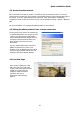
Quick Installation Guide 3. Select the camera on the list and click right button of the mouse. The pop-up menu displays as below. 4. Select Assign IP. The Assign IP window displays. Enter the required IP address.
Quick Installation Guide 4. Operation The V-CELL-IP Camera can be used with Windows® operating system and browsers. The recommended browsers are Internet Explorer®, Safari®, Firefox®, Opera and Google Chrome® with Windows. 4.1 Access from a browser 1. 2. 3. Start a browser (i.e., Internet Explorer). Enter the IP address or host name of the V-CELL-IP Camera in the Location/Address field of your browser. A starting page displays. Click Live View or Setup to enter web page.
Quick Installation Guide 4.2. Access from the Internet Once connected, the V-CELL-IP Camera is accessible on your local network (LAN). To access the camera from the Internet you must configure your broadband router to allow incoming data traffic to the camera. To do this, enable the NAT-traversal feature, which will attempt to automatically configure the router to allow access to the camera. This is enabled from Setup > System > Network > NAT. For more information, see “3.5.
Quick Installation Guide 1) General controls Live View Page Search & Playback Page Setup Page Help Page The video drop-down list allows you to select a customized or pre-programmed video stream on the live view page. Stream profiles are configured under Setup > Basic Configuration > Video & Image. See Basic Configuration in the User manual for more information. The resolution drop-down list allows you to select the most suitable video resolution to be displayed on Live View page.
Quick Installation Guide 4.5 Network Camera Setup This section describes how to configure the V-CELL-IP Camera. It is intended for Administrators, who have unrestricted access to all the Setup tools, and Operators, who have access to the settings for Basic, Live View, Video & Image, Event, and System Configuration. You can configure the V-CELL-IP Camera by clicking Setup in the top right-hand corner of the Live View page. Click on this page to access the online help that explains the Setup tools.
Vicon Industries Inc. For office locations, visit the website: www.vicon-security.