
User's Manual

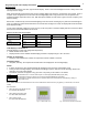
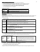


Table Of Contents
- Viconics
- Part
- Numbers
- 1. (None): No function will be associated with the input
- 4. (Filter): a backlit flashing Filter alarm will be displayed on the thermostat LCD screen when the input is energized. It can be tied to a differential pressure switch that monitor filters
- 5. (Service): a backlit flashing Service alarm will be displayed on the thermostat LCD screen when the input is energized. It can be tied in to the AC unit control card, which provides an alarm in case of malfunction.
- 1. (None): No function will be associated with the input
- 2. (COC/NH) Change over dry contact. Normally Heat: Used for hot / cold water change over switching in 2 pipe systems.
- Contact closed = Cold water present
- Only used and valid if system is setup as 2 pipes. Parameter ( Pipe No ) set as 2 pipes.
- 3. (COC/NC) Change over dry contact. Normally Cool: Used for hot / cold water or air change over switching in 2 pipe systems.
- Contact closed = Hot water present
- Only used and valid if system is setup as 2 pipes. Parameter ( Pipe No ) set as 2 pipes.
- 4. (COS) Change over analog sensor: Used for hot / cold water or air change over switching in 2 pipe systems.
- Only used and valid if system is setup as 2 pipes. Parameter ( Pipe No ) set as 2 pipes.
- 5. (SS) Supply air sensor monitoring: Used for supply air temperature monitoring.
- Only used for network reporting of the supply air temperature. Has no internal function in the thermostat.
- Range is: 0 to 500
- This parameter (Personal Area Network Identification) is used to link specific thermostats to a single specific Viconics wireless gateway ( VWG ) For every thermostat reporting to a gateway ( maximum of 30 thermostats per gateway ), be sure you set the SAME PAN ID value both at the gateway and the thermostat(s).
- Range is: 10 to 26
- Viconics recommends using only the 2 last channels ( 25-2575MHz and 26-2580MHz )
- Range is: 0 to 254
- This parameter / function is not currently supported by the wireless thermostats.
- BI1
- Default value = None
- (None): No function will be associated with the input
- (Filter): a backlit flashing Filter alarm will be displayed on the thermostat LCD screen when the input is energized. It can be tied to a differential pressure switch that monitor filters
- (Service): a backlit flashing Service alarm will be displayed on the thermostat LCD screen when the input is energized. It can be tied in to the AC unit control card, which provides an alarm in case of malfunction.
- UI3
- Default value = None
- (None): No function will be associated with the input
- (COC/NH) Change over dry contact. Normally Heat: Used for hot / cold water or air change over switching in 2 pipe systems.
- Contact closed = Cold water or air present
- Only used and valid if system is setup as 2 pipes. Parameter ( Pipe No ) set as 2 pipes.
- (COC/NC) Change over dry contact. Normally Cool: Used for hot / cold water or air change over switching in 2 pipe systems.
- Contact closed = Hot water present
- Only used and valid if system is setup as 2 pipes. Parameter (Pipe No ) set as 2 pipes.
- (COS) Change over analog sensor: Used for hot / cold water or air change over switching in 2 pipe systems.
- Only used and valid if system is setup as 2 pipes. Parameter (Pipe No ) set as 2 pipes.
- (SS) Supply air sensor monitoring: Used for supply air temperature monitoring.
- 2.0 Pipes, will limit the number of sequences of operation available from 0 to 3

16
aux cont
Auxiliary contact function &
configuration
Default value = 0 Not Used
0 Aux contact function used for reheat
IF SEQUENCE IS SET TO REHEAT THROUGH NETWORK OR LOCAL
, Ignore
this parameter
The output will directly follow the occupancy of the thermostat
1 Auxiliary NO, Occ or St-By = Contact Closed / Unoccupied = Contact Opened
2 Auxiliary NC, Occ or St-By = Contact Opened / Unoccupied = Contact Closed
Output to follow directly main occupancy and Fan on command
Typically used for 2 position fresh air damper applications.
3 Auxiliary NO, Occ or St-By & Fan On = Contact Closed / Unoccupied & Fan On
or Off = Contact Opened
4 Auxiliary NC, Occ or St-By & Fan On = Contact Opened / Unoccupied & Fan
On or Off = Contact Closed
Output to follow secondary network occupancy command
5 Auxiliary On/Off Control through auxiliary network command. The output can
be commanded through the network for any required auxiliary functions through a
separate & dedicated network variable.
FL time
For floating models
VT73xxC5x00(x) only
Default value: 1.5 minutes
Floating actuator timing
Maximum stroke time of floating valve actuator.
Range is: 0.5 to 9.0 minutes in 0.5 minutes increment
cph
On/Off devices cycles per hour
For On/Off models & sequences
VT73xxC5x00(x) only
Default value = 4 C.P.H.
Will set the maximum number cycles per hour under normal control operation. It
represents the maximum number of cycles that the equipment will turn ON and
OFF in one hour.
Note that a higher C.P.H will represent a higher accuracy of control at the expense
of wearing mechanical components faster.
Range is: 3, 4, 5, 6,7 & 8 C.P.H.
RA/DA
For Analog models
VT73xxF5x00(x) only
Default value: DA signal
Reverse acting or Direct acting signal for Analog output signals
DA = Direct acting, 0 to 100 % = 0 to 10 Vdc
RA = Reverse acting, 0 to 100 % = 10 to 0 Vdc
Reheat
Default value: 0 = 15 minute
Sets the reheat output time base
Valid only if reheat sequences are enabled
0 = 15 minutes
1 = 10 seconds for Solid state relays
UI3 dis
Display UI3 value.
Used as diagnostic / service help to troubleshoot and diagnose sensor operation
Supply or change over temperature when UI3 is configured as an analog input
( SS or COS )