
User's Manual

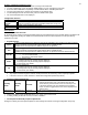


Table Of Contents
- Viconics
- Part
- Numbers
- 1. (None): No function will be associated with the input
- 4. (Filter): a backlit flashing Filter alarm will be displayed on the thermostat LCD screen when the input is energized. It can be tied to a differential pressure switch that monitor filters
- 5. (Service): a backlit flashing Service alarm will be displayed on the thermostat LCD screen when the input is energized. It can be tied in to the AC unit control card, which provides an alarm in case of malfunction.
- 1. (None): No function will be associated with the input
- 2. (COC/NH) Change over dry contact. Normally Heat: Used for hot / cold water change over switching in 2 pipe systems.
- Contact closed = Cold water present
- Only used and valid if system is setup as 2 pipes. Parameter ( Pipe No ) set as 2 pipes.
- 3. (COC/NC) Change over dry contact. Normally Cool: Used for hot / cold water or air change over switching in 2 pipe systems.
- Contact closed = Hot water present
- Only used and valid if system is setup as 2 pipes. Parameter ( Pipe No ) set as 2 pipes.
- 4. (COS) Change over analog sensor: Used for hot / cold water or air change over switching in 2 pipe systems.
- Only used and valid if system is setup as 2 pipes. Parameter ( Pipe No ) set as 2 pipes.
- 5. (SS) Supply air sensor monitoring: Used for supply air temperature monitoring.
- Only used for network reporting of the supply air temperature. Has no internal function in the thermostat.
- Range is: 0 to 500
- This parameter (Personal Area Network Identification) is used to link specific thermostats to a single specific Viconics wireless gateway ( VWG ) For every thermostat reporting to a gateway ( maximum of 30 thermostats per gateway ), be sure you set the SAME PAN ID value both at the gateway and the thermostat(s).
- Range is: 10 to 26
- Viconics recommends using only the 2 last channels ( 25-2575MHz and 26-2580MHz )
- Range is: 0 to 254
- This parameter / function is not currently supported by the wireless thermostats.
- BI1
- Default value = None
- (None): No function will be associated with the input
- (Filter): a backlit flashing Filter alarm will be displayed on the thermostat LCD screen when the input is energized. It can be tied to a differential pressure switch that monitor filters
- (Service): a backlit flashing Service alarm will be displayed on the thermostat LCD screen when the input is energized. It can be tied in to the AC unit control card, which provides an alarm in case of malfunction.
- UI3
- Default value = None
- (None): No function will be associated with the input
- (COC/NH) Change over dry contact. Normally Heat: Used for hot / cold water or air change over switching in 2 pipe systems.
- Contact closed = Cold water or air present
- Only used and valid if system is setup as 2 pipes. Parameter ( Pipe No ) set as 2 pipes.
- (COC/NC) Change over dry contact. Normally Cool: Used for hot / cold water or air change over switching in 2 pipe systems.
- Contact closed = Hot water present
- Only used and valid if system is setup as 2 pipes. Parameter (Pipe No ) set as 2 pipes.
- (COS) Change over analog sensor: Used for hot / cold water or air change over switching in 2 pipe systems.
- Only used and valid if system is setup as 2 pipes. Parameter (Pipe No ) set as 2 pipes.
- (SS) Supply air sensor monitoring: Used for supply air temperature monitoring.
- 2.0 Pipes, will limit the number of sequences of operation available from 0 to 3

17
Specifications
Thermostat power requirements: 19-30 Vac 50 or 60 Hz; 2 VA Class 2
Operating conditions: 0 °C to 50 °C ( 32 °F to 122 °F )
0% to 95% R.H. non-condensing
Storage conditions: -30 °C to 50 °C ( -22 °F to 122 °F )
0% to 95% R.H. non-condensing
Temperature sensor: Local 10 K NTC thermistor
Temperate sensor resolution: ± 0.1 °C ( ± 0.2 °F )
Temperature control accuracy: ± 0.5 ° C ( ± 0.9 °F ) @ 21 °C ( 70 °F ) typical calibrated
Humidity sensor and calibration: Single point calibrated bulk polymer type sensor
Humidity sensor precision: Reading range from 10-90 % R.H. non-condensing
10 to 20% precision is 10%
20% to 80% precision is 5%
80% to 90% precision is 10%
Humidity sensor stability Less than 1.0 % yearly (typical drift)
Dehumidification setpoint range: 30% to 95% R.H.
Occ, Stand-By and Unocc cooling setpoint range: 12.0 to 37.5 °C ( 54 to 100 °F )
Occ, Stand-By and Unocc heating setpoint range: 4.5 °C to 32 °C ( 40 °F to 90 °F )
Room and outdoor air temperature display range -40 °C to 50 °C ( -40 °F to 122 °F )
Proportional band for room temperature control: Cooling & Heating: 1.8°C ( 3.2°F )
Binary inputs: Dry contact across terminal BI1, BI2 & UI3 to Scom
Contact output rating: Fan relay output: 30 Vac, 1 Amp. Maximum, 3 Amp. in-rush
Valve triac output: 30 Vac, 1 Amp. Maximum, 3 Amp. in-rush
Valve analog: 0 to 10 Vdc into 2KΩ resistance min.
Wire gauge 18 gauge maximum, 22 gauge recommended
Dimensions: 4.94” x 3.38” x 1.13”
Approximate shipping weight: 0.75 lb ( 0.34 kg )
Agency Approvals all models:
UL: UL 873 (US) and CSA C22.2 No. 24 (Canada), File E27734
with CCN XAPX (US) and XAPX7 (Canada)
Industry Canada: ICES-003 (Canada)
Agency Approvals Stand-Alone, BACnet & LON models
FCC: Compliant to CFR 47, Part 15, Subpart B, Class A (US)
CE: EMC Directive 89/336/EEC (Europe Union)
C-Tick: AS/NZS CISPR 22 Compliant (Australia / New Zealand)
Supplier Code Number N10696
Agency Approvals Wireless models
FCC: Compliant to: Part 15, Subpart C
THIS DEVICE COMPLIES WITH PART 15 OF THE FCC RULES. OPERATION IS SUBJECT TO THE FOLLOWING TWO
CONDITIONS: (1) THIS DEVICE MAY NOT CAUSE HARMFUL INTERFERENCE, AND (2) THIS DEVICE MUST ACCEPT
ANY INTERFERENCE RECEIVED, INCLUDING INTERFERENCE THAT MAY CAUSE UNDESIRED OPERATION.
Drawing & Dimensions
3.38" [86 mm]
1.13" [29 mm]
4.94" [125 mm]
Fig.13 – Thermostat dimensions
Important Notice
All VT7300 series
controls are for use as
operating controls only
and are not safety
devices. These instruments have
undergone rigorous tests and
verifications prior to shipment to
ensure proper and reliable operation in
the field. Whenever a control failure
could lead to personal injury and/or
loss of property, it becomes the
responsibility of the user / installer /
electrical system designer to
incorporate safety devices ( such as
relays, flow switch, thermal
protections, etc…) and/or alarm
system to protect the entire system
against such catastrophic failures.
Tampering of the devices or miss
application of the device will void
warranty.