
User's Manual


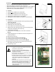
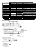


Table Of Contents
- Viconics
- Part
- Numbers
- 1. (None): No function will be associated with the input
- 4. (Filter): a backlit flashing Filter alarm will be displayed on the thermostat LCD screen when the input is energized. It can be tied to a differential pressure switch that monitor filters
- 5. (Service): a backlit flashing Service alarm will be displayed on the thermostat LCD screen when the input is energized. It can be tied in to the AC unit control card, which provides an alarm in case of malfunction.
- 1. (None): No function will be associated with the input
- 2. (COC/NH) Change over dry contact. Normally Heat: Used for hot / cold water change over switching in 2 pipe systems.
- Contact closed = Cold water present
- Only used and valid if system is setup as 2 pipes. Parameter ( Pipe No ) set as 2 pipes.
- 3. (COC/NC) Change over dry contact. Normally Cool: Used for hot / cold water or air change over switching in 2 pipe systems.
- Contact closed = Hot water present
- Only used and valid if system is setup as 2 pipes. Parameter ( Pipe No ) set as 2 pipes.
- 4. (COS) Change over analog sensor: Used for hot / cold water or air change over switching in 2 pipe systems.
- Only used and valid if system is setup as 2 pipes. Parameter ( Pipe No ) set as 2 pipes.
- 5. (SS) Supply air sensor monitoring: Used for supply air temperature monitoring.
- Only used for network reporting of the supply air temperature. Has no internal function in the thermostat.
- Range is: 0 to 500
- This parameter (Personal Area Network Identification) is used to link specific thermostats to a single specific Viconics wireless gateway ( VWG ) For every thermostat reporting to a gateway ( maximum of 30 thermostats per gateway ), be sure you set the SAME PAN ID value both at the gateway and the thermostat(s).
- Range is: 10 to 26
- Viconics recommends using only the 2 last channels ( 25-2575MHz and 26-2580MHz )
- Range is: 0 to 254
- This parameter / function is not currently supported by the wireless thermostats.
- BI1
- Default value = None
- (None): No function will be associated with the input
- (Filter): a backlit flashing Filter alarm will be displayed on the thermostat LCD screen when the input is energized. It can be tied to a differential pressure switch that monitor filters
- (Service): a backlit flashing Service alarm will be displayed on the thermostat LCD screen when the input is energized. It can be tied in to the AC unit control card, which provides an alarm in case of malfunction.
- UI3
- Default value = None
- (None): No function will be associated with the input
- (COC/NH) Change over dry contact. Normally Heat: Used for hot / cold water or air change over switching in 2 pipe systems.
- Contact closed = Cold water or air present
- Only used and valid if system is setup as 2 pipes. Parameter ( Pipe No ) set as 2 pipes.
- (COC/NC) Change over dry contact. Normally Cool: Used for hot / cold water or air change over switching in 2 pipe systems.
- Contact closed = Hot water present
- Only used and valid if system is setup as 2 pipes. Parameter (Pipe No ) set as 2 pipes.
- (COS) Change over analog sensor: Used for hot / cold water or air change over switching in 2 pipe systems.
- Only used and valid if system is setup as 2 pipes. Parameter (Pipe No ) set as 2 pipes.
- (SS) Supply air sensor monitoring: Used for supply air temperature monitoring.
- 2.0 Pipes, will limit the number of sequences of operation available from 0 to 3

3
Installation
• Remove security screw on the bottom of thermostat cover.
• Open up by pulling on the bottom side of thermostat.
• Remove Assembly and remove wiring terminals from sticker. (Fig. 3)
• Please note the FCC ID and IC label installed in the cover upon
removal of cover for the wireless products.
A) Location:
1- Should not
be installed on an outside wall.
2- Must be installed away from any heat source.
3- Should not be installed near an air discharge grill.
4- Should not be affected by direct sun radiation.
5- Nothing must restrain vertical air circulation to the thermostat.
B) Installation:
1- Swing open the thermostat PCB to the left by pressing the PCB
locking tabs. (Fig. 4)
2- Pull out cables 6” out of the wall.
3- Wall surface must be flat and clean.
4- Insert cable in the central hole of the base.
5- Align the base and mark the location of the two mounting holes
on the wall. Install proper side of base up.
6- Install anchors in the wall.
7- Insert screws in mounting holes on each side of the base.
(Fig. 4)
8- Gently swing back the circuit board on the base and push on it
until the tabs lock it.
10- Strip each wire 1/4 inch.
11- Insert each wire according to wiring diagram.
13- Gently push back into hole excess wring (Fig. 5)
14- Re-Install wiring terminals in correct location. (Fig. 5)
15- Reinstall the cover (top side first) and gently push back extra
wire length into the hole in the wall.
16- Install security screw.
• If replacing an old thermostat, label the wires before
removal of the old thermostat.
• Electronic controls are static sensitive devices.
Discharge yourself properly before manipulation and
installing the thermostat.
• Short circuit or wrong wiring may permanently damage
the thermostat or the equipment.
• Anti-short cycling can be set to 0 minutes for equipment
that posses their own anti cycling timer. Do not use that
value unless the equipment is equipped with such
internal timer. Failure to do so can damage the
equipment.
• All VT7000 series thermostats are to be used only as
operating controls. Whenever a control failure could
lead to personal injury and/or loss of property, it
becomes the responsibility of the user to add safety
devices and/or alarm system to protect against such
catastrophic failures.
Fig.3
Fig.5
Location of PCB retaining tabs
Re-install terminal blocks
Thermostat assembly
(VT7300F5000B shown)
Fig.4
Fig.6