
User's Manual


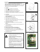
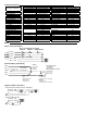


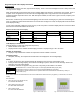
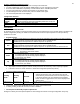
Table Of Contents
- Viconics
- Part
- Numbers
- 1. (None): No function will be associated with the input
- 4. (Filter): a backlit flashing Filter alarm will be displayed on the thermostat LCD screen when the input is energized. It can be tied to a differential pressure switch that monitor filters
- 5. (Service): a backlit flashing Service alarm will be displayed on the thermostat LCD screen when the input is energized. It can be tied in to the AC unit control card, which provides an alarm in case of malfunction.
- 1. (None): No function will be associated with the input
- 2. (COC/NH) Change over dry contact. Normally Heat: Used for hot / cold water change over switching in 2 pipe systems.
- Contact closed = Cold water present
- Only used and valid if system is setup as 2 pipes. Parameter ( Pipe No ) set as 2 pipes.
- 3. (COC/NC) Change over dry contact. Normally Cool: Used for hot / cold water or air change over switching in 2 pipe systems.
- Contact closed = Hot water present
- Only used and valid if system is setup as 2 pipes. Parameter ( Pipe No ) set as 2 pipes.
- 4. (COS) Change over analog sensor: Used for hot / cold water or air change over switching in 2 pipe systems.
- Only used and valid if system is setup as 2 pipes. Parameter ( Pipe No ) set as 2 pipes.
- 5. (SS) Supply air sensor monitoring: Used for supply air temperature monitoring.
- Only used for network reporting of the supply air temperature. Has no internal function in the thermostat.
- Range is: 0 to 500
- This parameter (Personal Area Network Identification) is used to link specific thermostats to a single specific Viconics wireless gateway ( VWG ) For every thermostat reporting to a gateway ( maximum of 30 thermostats per gateway ), be sure you set the SAME PAN ID value both at the gateway and the thermostat(s).
- Range is: 10 to 26
- Viconics recommends using only the 2 last channels ( 25-2575MHz and 26-2580MHz )
- Range is: 0 to 254
- This parameter / function is not currently supported by the wireless thermostats.
- BI1
- Default value = None
- (None): No function will be associated with the input
- (Filter): a backlit flashing Filter alarm will be displayed on the thermostat LCD screen when the input is energized. It can be tied to a differential pressure switch that monitor filters
- (Service): a backlit flashing Service alarm will be displayed on the thermostat LCD screen when the input is energized. It can be tied in to the AC unit control card, which provides an alarm in case of malfunction.
- UI3
- Default value = None
- (None): No function will be associated with the input
- (COC/NH) Change over dry contact. Normally Heat: Used for hot / cold water or air change over switching in 2 pipe systems.
- Contact closed = Cold water or air present
- Only used and valid if system is setup as 2 pipes. Parameter ( Pipe No ) set as 2 pipes.
- (COC/NC) Change over dry contact. Normally Cool: Used for hot / cold water or air change over switching in 2 pipe systems.
- Contact closed = Hot water present
- Only used and valid if system is setup as 2 pipes. Parameter (Pipe No ) set as 2 pipes.
- (COS) Change over analog sensor: Used for hot / cold water or air change over switching in 2 pipe systems.
- Only used and valid if system is setup as 2 pipes. Parameter (Pipe No ) set as 2 pipes.
- (SS) Supply air sensor monitoring: Used for supply air temperature monitoring.
- 2.0 Pipes, will limit the number of sequences of operation available from 0 to 3

4
Terminal identification
V
iconics Part Numbers
V
T73xxA5x00(x)
V
T73xxC5x00(x)
V
iconics Number
V
T73xxF5x00(x)
Description / Application 2 & 4 Pipe On/Off 2 & 4 Pipe Floating Description / Application 2 & 4 Pipe Analog
2 & 4 Pipe On/Off
Internal Temperature X
X
Internal Temperature
X
Internal Humidity Model Dependent Internal Humidity Model Dependent
1- High Fan Speed
Fan-H Fan-H
1- High Fan Speed
Fan-H
2- Medium Fan Speed
Fan-M Fan-M
2- Medium Fan Speed
Fan-M
3- Low Fan Speed
Fan-L Fan-L
3- Low Fan Speed
Fan-L
4- 24 V~ Hot
24 V~ Hot 24 V~ Hot
4- 24 V~ Hot
24 V~ Hot
5- 24 V~ Com 24 V~ Com 24 V~ Com 5- 24 V~ Com 24 V~ Com
6- Aux BO 5 BO 5-Aux BO 5-Aux 6- Aux BO 5 BO 5-Aux
7- Aux BO 5
BO 5-Aux BO 5-Aux
7- Aux BO 5
BO 5-Aux
8- BO 3 Open Heat
BO 3 BO 3
9- BO 4 Close Heat
BO 4
9- AO 2 Heat
AO 2
10- BO 1 Open Cool
BO 1
10- AO 1 Cool
AO 1
11- BO 2 Close Cool BO 2 BO 2 Not used Blank
Blank
12- BI #1 BI 1 BI 1 12- BI #1 BI 1
13- RS
RS RS
13- RS
RS
14- Scom
Scom Scom
14- Scom
Scom
15- BI #2
BI 2 BI 2
15- BI #2
BI 2
16- UI #3 COS / COC /SS
UI 3 UI 3
16- UI #3 COS / COC /SS
UI 3
Wiring
Fan-H
Fan-M
Fan-L
24 V~ Hot
24 V~ Com
24 V~ transformer relay pack
3 speed 2 speed Single speed
High
Med
Low
High
Low
High
Power & Fan ( All models )
Remote inputs ( All models )
BI 1
RS
Scom
BI 2
UI 3
OR
Contact
- Rem NSB
- Motion
- Window
Contact
- Door
- Remote Override
- Filter alarm
- service alarm
Remote wall sensor
- S3010W1000
- S3020W1000
SS ( supply sensor )
- S1010E1000
- S2000D1000
COS ( changeover sensor )
- S1010E1000
COC/NH
- Normally heat
- Closed contact = cold water
COC/NC
- Normally cool
- Closed contact = heat water
#4 24 V~ Hot
#5 24 V~ Com
#6
#7
#4 24 V~ Hot
#5 24 V~ Com
#6
#7
Auxiliary output ( All models )
- Dry contact to end device 24 V~ maximum
- 24 Vac power to relay
R
R