
User's Manual


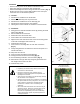
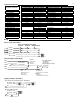


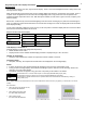
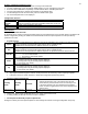
Table Of Contents
- Viconics
- Part
- Numbers
- 1. (None): No function will be associated with the input
- 4. (Filter): a backlit flashing Filter alarm will be displayed on the thermostat LCD screen when the input is energized. It can be tied to a differential pressure switch that monitor filters
- 5. (Service): a backlit flashing Service alarm will be displayed on the thermostat LCD screen when the input is energized. It can be tied in to the AC unit control card, which provides an alarm in case of malfunction.
- 1. (None): No function will be associated with the input
- 2. (COC/NH) Change over dry contact. Normally Heat: Used for hot / cold water change over switching in 2 pipe systems.
- Contact closed = Cold water present
- Only used and valid if system is setup as 2 pipes. Parameter ( Pipe No ) set as 2 pipes.
- 3. (COC/NC) Change over dry contact. Normally Cool: Used for hot / cold water or air change over switching in 2 pipe systems.
- Contact closed = Hot water present
- Only used and valid if system is setup as 2 pipes. Parameter ( Pipe No ) set as 2 pipes.
- 4. (COS) Change over analog sensor: Used for hot / cold water or air change over switching in 2 pipe systems.
- Only used and valid if system is setup as 2 pipes. Parameter ( Pipe No ) set as 2 pipes.
- 5. (SS) Supply air sensor monitoring: Used for supply air temperature monitoring.
- Only used for network reporting of the supply air temperature. Has no internal function in the thermostat.
- Range is: 0 to 500
- This parameter (Personal Area Network Identification) is used to link specific thermostats to a single specific Viconics wireless gateway ( VWG ) For every thermostat reporting to a gateway ( maximum of 30 thermostats per gateway ), be sure you set the SAME PAN ID value both at the gateway and the thermostat(s).
- Range is: 10 to 26
- Viconics recommends using only the 2 last channels ( 25-2575MHz and 26-2580MHz )
- Range is: 0 to 254
- This parameter / function is not currently supported by the wireless thermostats.
- BI1
- Default value = None
- (None): No function will be associated with the input
- (Filter): a backlit flashing Filter alarm will be displayed on the thermostat LCD screen when the input is energized. It can be tied to a differential pressure switch that monitor filters
- (Service): a backlit flashing Service alarm will be displayed on the thermostat LCD screen when the input is energized. It can be tied in to the AC unit control card, which provides an alarm in case of malfunction.
- UI3
- Default value = None
- (None): No function will be associated with the input
- (COC/NH) Change over dry contact. Normally Heat: Used for hot / cold water or air change over switching in 2 pipe systems.
- Contact closed = Cold water or air present
- Only used and valid if system is setup as 2 pipes. Parameter ( Pipe No ) set as 2 pipes.
- (COC/NC) Change over dry contact. Normally Cool: Used for hot / cold water or air change over switching in 2 pipe systems.
- Contact closed = Hot water present
- Only used and valid if system is setup as 2 pipes. Parameter (Pipe No ) set as 2 pipes.
- (COS) Change over analog sensor: Used for hot / cold water or air change over switching in 2 pipe systems.
- Only used and valid if system is setup as 2 pipes. Parameter (Pipe No ) set as 2 pipes.
- (SS) Supply air sensor monitoring: Used for supply air temperature monitoring.
- 2.0 Pipes, will limit the number of sequences of operation available from 0 to 3

9
Programming and status display instructions
Status display
The thermostat features a two-line, eight-character display. There is a low level backlight level that is always active and
can only be seen at night.
When left unattended, the thermostat has an auto scrolling display that shows the actual status of the system. There is
an option in the configuration menu to lockout the scrolling display and to only present the room temperature and
conditional outdoor temperature to the user. With this option enabled, no local status is given of mode, occupancy and
relative humidity.
Each item is scrolled one by one with the back lighting in low level mode. Pressing any key will cause the back light to
come on to high level. When left unattended for 10 seconds after changes are made, the display will resume automatic
status display scrolling.
To turn on the back light to high level, press any key on the front panel. The back lit display will return to low level when
the thermostat is left unattended for 45 seconds
Sequence of auto-scroll status display:
Room & Humidity System Mode Schedule Status Outdoor Temperature Alarms
x.x °C or °F Sys mode Occupied Outdoor Service
XX % RH Auto x.x °C or°F
If humidity display
enabled
Sys mode
Cool
Stand-By
Network value only
Filter
RoomTemp
x.x °C or °F
Sys mode
heat
Unoccup
Window
If humidity display is not
enabled
Sys mode
off
Override
% RH display is conditional to:
(Humidity display is model and configuration dependent)
• Model with RH sensor built in
• Display function can be enabled with RH display parameter. Displayed range is 10 to 90 % RH
Outdoor air temperature
• Display is only enabled when outdoor air temperature network variable is received.
Occupancy Status
• Occupied, Stand-By, Unoccupied and Override status are displayed on the scrolling display.
Alarms
• If alarms are detected, they will automatically be displayed at the end of the status display scroll.
• During an alarm message display, the backlit screen will light up at the same time as the message and shut off
during the rest of the status display.
• Two alarms maximum can appear at any given time. The priority for the alarms is as follows:
Service
Indicates that there is a service alarm as per one of the programmable binary input ( BI2 )
Filter
Indicates that the filters are dirty as per one of the programmable binary input ( BI2 )
Window
Indicates that the outside window or door is opened and that the thermostat has cancelled any cooling or
heating action ( BI1 )
Three status LED’s on the thermostat cover are used to indicate the status of the fan ( any speed ), a call for heat, or a call for
cooling.
Fan coil models
• When any of the fan speeds are ON,
the FAN LED will illuminate.
• When heating & reheat is ON,
the HEAT LED will illuminate.
• When cooling is ON,
the COOL LED will illuminate.
Fig.11 – Hotel models °C/°F Fig. 12 Commercial models with Override