Viconics BACnet Zoning System Application Guide VZ7260X5x00B and VZ7656X5000B Controllers VBZS_Rel2_Application_Guide-E04 (R1 Issue Date: January 10th, 2012) 1
Table of Contents: Please refer to the installation manuals of the zoning system controllers for all required information related to wiring, installation, commissioning and integration: • For detailed information on the Viconics VZ72xx zone controller, please refer and read the VZ72xx product guide. Installation and commissioning information is available on document: LIT-VZ7260X-Exx • For detailed information on the Viconics VZ76xx RTU controller, please refer and read the VZ76xx product guide.
1) System Overview and Architecture The Viconics Zoning System product is comprised of two controller types. • The VZ7260X5x00B Zoning controller • The VZ7656X1000B RTU / HP controller When combined, they deliver a simple and efficient demand based system implementation which controls pressure dependent VAV zones with roof top units (RTU). The system is designed to work with small to medium sized RTU staged heating and cooling equipment (2 to 20 tons).
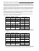
• Proper wiring of all components as per the installation manual • Proper network wires pulled through all devices communication connections Zone Controllers Available Models & Features: Viconics Part Number Control Outputs PIR Cover VZ7260F5000B VZ7260F5500B VZ7260C5000B 2 x Analog 0 to 10 VDC 1 x Auxiliary reheat contact PIR cover ready.
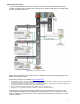
BACnet System Overview Viconics VZ72605x00B Zone controllers are used in conjunction with the VZ7656X1000B roof top controller controllers. When combined, they are designed for operate typical single or multistage RTUs and their associated local zones. Typical BACnet zoning system installation Please refer to the following Viconics documents for detailed information and design guidelines on the BACnet zoning system version: The following documents are available at: www.viconics.
1A) Initial Design Considerations The scope of this document is not intended to be a resource or white paper on VAV zoning system design. There are many good resources available on the subject of VAV zoning systems and their associated advantages and disadvantages. Please consult these resources for further information on this subject.
1C) Local Zone with Terminal Reheat or without Terminal Reheat Including or excluding use of terminal reheat is dictated by design criteria’s of the installer. The use of terminal reheat in a VAV system will always result in a more comfortable set-up for the occupants of the space. However this may not be practical from a cost standpoint or regional requirements.
1E) By-Pass Damper Design Rules A bypass damper is an airflow regulating device connected between the supply and return ducts. The bypass damper will automatically open and bypass supply air normally delivered to the zone directly from the supply to the return on a pressure rise when the VAV zone dampers are closing. The by-pass damper should be sized to allow at least 70 to 80% of the nominal airflow of the RTU.
2A) Demand Based Heating and Cooling Systems System operation as a whole consists of selecting which zone controllers will have heating and cooling weighted votes used by the RTU controller to which they are attached. The weighted heating and cooling demand values from the selected master zones are then used by the RTU controller to determine if heating or cooling action is required for the system as a whole. Both internal and external zones are typically serviced by the same unit.
configuration. • If the RTU is set to Control Type = Highest demand, the current action delivered by the RTU will be heating. • If the RTU is set to Control Type = Average of 3 Highest demand, the current action delivered by the RTU will be cooling.
allow the local heating and cooling demands to be sent to the RTU controller. This will have the effect of re-starting the central system and allowing delivery of hot or cold air based on the current local demand. Pressing the override key allows an override for this zone controller only. All other zones although being delivered hot or cold air will still be in unoccupied mode and using their unoccupied set points.
2C) Zone Set point Limits It cannot be stressed enough that must take caution and properly explain to the user or tenants of the building or system that a demand based heating or cooling system is designed to respond to actual local demand of a number of selected zones. Even if the local demand cannot be meet by the central system. For the following reason it is recommended to “limit” the set point adjustments of any zone controller that have actual demand voting capacity at the RTU controller.
o o Zones selected to be masters for demand calculations should represent either: - Typical zones or areas that will be exposed to some of the highest peak heating and cooling loads. - Zones or areas that represent a significant portion of the equipment peak load capacity. Example, if a system has five zones where a single zone represents ½ of the total MAX CFM of the equipment, then for sure this zone needs to be master to the system.
2E) Minimum, Maximum and Heat flow Adjustments Although system balancing can be accomplished by utilizing the controller’s built in configuration settings. It is recommended to add a balancing side-takeoff damper on all zones. This will ensure that any supplementary air can be reduced and will limit excessive noise due to airflow if the zones or associated ductwork were improperly sized. Minimum Position Ajustement (Min Pos) This parameter sets the minimum amount of air being delivered to the zone.
- The selected zone dampers minimum position has a direct impact on the temperature stability for certain zones. Having a minimum position selected may produce an over cooling or over heating effect. This effect is created when the primary air temperature is in the inverse mode than that which the zone currently requires. An example of this is when an internal zone is requesting cooling during winter while the RTU is supplying hot air for the external zones.
Please note: - 0 to 100 % is directly converted to 0 to 10 VDC on the VAV damper output. If the actuator has a positioning input range of 2 to 10 VDC, then entering 50% minimum position is not directly converted to 50% VAV damper position.
2 G) Passive Infra Red Motion Detector Cover (PIR) The Viconics zone controllers are compatible with the new Viconics PIR (Passive Infra Red) cover accessory. Controllers equipped with a PIR cover provide advanced active occupancy logic, which can automatically switch occupancy levels from occupied to stand-by as required when local activity is detected in the room. This advanced occupancy functionality provides advantageous energy savings during occupied hours without sacrificing occupant comfort.
2 H) AI4 CO2 / Other Sensor Input Operation AI4 CO2 Sensor Input Operation The VT76XXE controller features a 0-10VDC input (AI4) that is used for monitoring using any 0-10VDC sensor or to control the building CO2level. Using any 0-10VDC value for monitoring If the AI4 input is used for monitoring purposes only (even if monitoring CO2 with a CO2 sensor), the AI4 parameter should be set to None (not CO2).
2 I) Disable Minimum Position parameter The VZ7260 zone controllers feature the DisMinPo (Disable Minimum Position) parameter that is used to enable/disable the minimum damper’s minimum position parameter setting if the zone sequence (heat/cool) is different than the controller’s demand (heat/cool). The goal of this parameter is to prevent overcooling or overheating of zones that have demands that differ from the general zone sequence due to the airflow through the damper opening (at the minimum position).
3) RTU Controllers VZ7656X1000B Operation The following information needs to be carefully read and properly understood if proper system commissioning is to be achieved. Unlike low end commercial or residential zoning controllers which typically only use two position demand or non-demand logic to initialize heating and cooling functions, Viconics VZ7656X1000B uses local PI zone demand(s) to operate heating and cooling stages.
3B) Occupancy and Overrides The occupancy of the zones is controlled by the schedule in the RTU controller. - When this schedule output value is unoccupied (as shown on the RTU controller display), then the attached zones will be unoccupied mode. - When this schedule output value is occupied (as shown on the per RTU controller display), then the attached zones will be either in occupied mode or stand-by mode if local PIR function is used.
3E) RTU Heating and Cooling Outdoor Air Temperature Lockouts H Lock and C Lock - Parameter C Lock temperature disables the cooling stages based on the outdoor temperature. - Parameter H Lock temperature disables the heating stages based on the outdoor temperature. RTU mode lockouts need to be properly set to keep heating or cooling equipment cycling to a minimum. It is the responsibility of the installer to decide if priority of the system will be given to comfort or not.
Also, the recorded RTU supply delta temperature and demand variances will always be higher when using a highest demand control type operation versus an average demand method. Energy consumption is also expected to be higher with a highest demand control type operation versus an average demand method of calculating the system requirements.
Variable Frequency Drive Operation: In this case the G fan output is used as an enable / disable output for the VFD. The VFD should be configured to be reverse acting: - Control signal = 0 VDC = VFD at high flow = Higher pressure. Control signal = 10 VDC = VFD at low flow = Lower pressure. When the VFD is disabled (Terminal G is off), the static pressure control loop is off and the VFD output is at 0VDC.
Economizer Control Mode Only If the fresh air damper is to be used only for free cooling purposes (economizer mode, without fresh air measurement station or CO2 control), only the Min Pos parameter and the free cooling sequence will be active. - The FA Range parameter should be set to 0 CFM. (Default Value = 0 CFM) - Set the Chngstpt parameter to desired value which free cooling is enabled.
Economizer Mode and Fresh Air Measurement Station If the fresh air damper is to be used for both free cooling and minimum fresh air volume control (economizer mode and fresh air measurement station, but without CO2 level control), only the Min FA parameter and the free cooling sequence will be active. - The FA Range parameter should be set to a value higher than 0 CFM (0 CFM disables the fresh air control). Min FA (minimum fresh air) parameter should be set to the desired level.
Economizer Mode and CO2 Level Control If the fresh air damper is to be used for both free cooling and CO2level control (economizer mode and CO2 level control, but without fresh air measurement station), only the Min Pos, Max Pos, Min CO2and Max CO2 parameters as well as the free cooling sequence will be active. - The FA Range parameter should be set to 0 CFM.
Economizer Mode, CO2 Level Control and Fresh Air Measurement Station If the fresh air damper is to be used for both free cooling and CO2 level control with a fresh air measurement station, only the Min FA, Max FA, Min CO2 and Max CO2 parameters as well as the free cooling sequence will be active. - The FA Range parameter should be set to something other than 0 CFM.
4) BACnet Communication Overview The Viconics VZ7260X5x00B and VZ7656X1000B controllers use a local BACnet RS485 MS-TP communication bus between all devices to insure proper communication and smooth data exchange of all required information for proper system operation. BACnet is "a data communication protocol for Building Automation and Control networks." A data communication protocol is a set of rules governing the exchange of data over a computer network.
4A) 3rd Party BACnet Integration BACnet being an open protocol also means that the Viconics zoning system products can be seamlessly integrated into any 3rd party BACnet supervision system. This enables the whole system to be integrated into an open building automation DDC system.
EOL: MS-TP network must be properly terminated. For daisy chain configurations, you must install an EOL (End of Line) resistor at each end of the daisy chain (The first and the last device). For a stand-alone system with only Viconics controllers installed on the communication network the value of the EOL resistor is 120 Ohms ¼ watt. For EOL values used with other non-Viconics devices on the network, please refer to the Viconics Integration Guide.
4C) Communication Status LED and Troubleshooting Each controller has a communication status service LED for troubleshooting purposes. Monitoring this LED will determine the network conditions for each individual device and will tell you if they are communicating properly with other devices on the network.
5B) Proper Commissioning RTU Controllers At the RTU level, care should be applied to insure the following: - Proper sizing of the RTU heating and cooling capacity to insure it will meet the highest instantaneous peak loads of the areas being served by the system. - Proper strategy and system layout of the mechanical system architecture. - Proper commissioning and verification of the by-pass system.
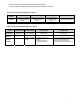
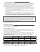
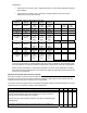
RTU Commissioning RTU mechanical cooling functional verification done Maximum Delta temperature ( return to supply temp ) for cooling stage #1: Maximum Delta temperature ( return to supply temp ) for cooling stage #1 & 2: Economizer cooling functional verification done Minimum position of economizer properly set? RTU controller Aux output used to disable minimum position of economizer check? RTU heating functional verification done Maximum Delta temperature ( return to supply temp ) for heating stage #1: Ma
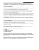
Zone Number ( ) Commissioning VAV damper actuator properly rigged and verified? ( opens & closes with demand ) Proper adjustments of zone side take off balancing damper? Proper balancing of zone minimum position? CFM = Proper balancing of zone maximum position? CFM = Proper balancing of zone MaxHeatflow position? (If reheat is used) CFM = Verification of Reheat (If reheat is used) Maximum Delta temperature of Reheat (If duct reheat is used) Important configuration property set? - Zone MAC: - ZoneBaud: - RTC
6B) Critical Point Checks To insure proper and reliable operation of the system, it is the responsibility of the system designer and or installer to properly verify all important milestones of the project. This includes all other contractual aspects for the system performed outside of the control system scope of work: - Design phase: load calculations and ductwork layout and sizing, equipment selection, etc…..