VC 3000 Series Line Voltage Sw itching Rela y Pack Controllers Installation Guide For Commercial and Lodging HVAC F a n C o i l Ap p l i c a t i o n s May 3 rd , 2012 / 028-0296-R6 CONTENTS Installation Communication Wiring to VTR73xxA Terminal Equipment Controller VC3xxx LED Operation Wiring of Remote Inputs to VC3504E and VC3404E Model Chart Terminals, Wire Identification & Ratings Typical Wiring Example Specifications Dimensions Important Notice 1 VC7300 Series-Installation Guide 2 4 4 5 6 7 8 9 9 1
I NSTALLATION IMPORTANT: ALL WIRING MUST CONFORM TO LOCAL AND NATIONAL ELECTRICAL CODE REGULATIONS. Please read the following instructions carefully before proceeding with the installation. Failure to follow the instructions could damage the product or cause a hazardous condition. Installation must be performed by a qualified service technician or electrician. Disconnect power supply before installing in order to prevent electrical shock.
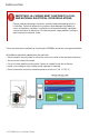
B) Outside of a junction box or electrical cabinet • Use the supplied lock nut to secure the transformer relay pack to the electrical junction box or to the electrical cabinet of the fan coil unit. C) Enclosed low voltage junction box type installation (if required by local codes) • Install the transformer relay pack inside a 4”x 4” junction box. • Cut one or both plastic mounting tabs if space is needed inside the enclosure.
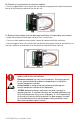
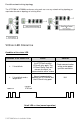
COMMUNICATION WIRING TO VTR73 XX A TERMINAL E QUIPMENT CONTROLLER Only one VC3xxxX relay pack with remote monitoring inputs can be used under a single VTR73xxA controller. All other slave units must be either VC3xxxX relay pack(s) WITHOUT remote inputs. A maximum of 10 VC3xxxX relay packs can be used for a single VTR73xxA terminal equipment controller. From the VTR73xxA to the first VC3xxxX o Existing or new field wires o 3 minimum required 14-22 Ga solid or stranded. Shield not necessary.
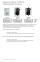
Possible network wiring topology The VTR7300 to VC3000 transformer relay pack can use any network wiring topology as required or based on topology of existing wires. VC3XXX LED OPERATION Condition of the status LED Condition of the Status LED Cause Solution Check communication wiring and or power cycle the controllers N/A 2 short blinks No communication between the VTR73xxA and the VC3xxxX relay pack.
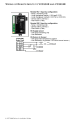
WIRING OF REMOTE INPUTS TO VC3504E AND VC3404E 6 VC7300 Series-Installation Guide
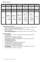
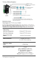
MODEL CHART Part # Applications Fan control Monitoring inputs VC3500E5000 VC3504E5000 VC3514E5000 Occ.
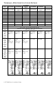
TERMINALS , WIRE I DENTIFICATION & RATINGS Part # VC3500E5000 VC3504E5000 VC3514E5000 Occupancy Output VC3400E5000 VC3404E5000 VC3300E5000 Slave Fan Unit Low Voltage Terminals No local inputs Low voltage inputs Low voltage inputs No local inputs Low voltage inputs No local inputs 1- Tx/Rx 1- Tx/Rx 1- Tx/Rx 1- Tx/Rx 1- Tx/Rx 1- Tx/Rx 2- 7 VDC 2- 7 VDC 2- 7 VDC 2- 7 VDC 2- 7 VDC 2- 7 VDC 3- Com 3- Com 3- Com 1 2 3 4 5 6 7 8 9 10 3- Com 3- Com 3- Com 4- RUI 1 4- RUI 1 4- RUI
TYPICAL W IRING E XAMPLE S PECIFICATIONS Power Supply: 90 to 277 VAC universal, 50-60 Hz Fan line voltage contact electrical ratings: Brown, Blue, Red wires ½ HP maximum Main heat and cool line voltage contact electrical ratings: Yellow wire 10A maximum Isolated heat line voltage contact electrical ratings: Orange wires 10A maximum Output ratings: -Heat Valve: (Orange wire): 10 Amps @ 277 VAC maximum -Cool Valve: (Yellow wire): 5 Amps @ 277 VAC maximum -Fan: (red, blue, brown wire(s)): 1/2 HP @ 277 V
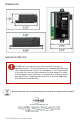
DIMENSIONS IMPORTANT NOTICE VC3000 series transformer relay packs are to be used only as operating controls. If installed incorrectly the intended application may fail or lead to personal injury or loss of property. It is the responsibility of the end user to ensure that the device has been properly installed and that proper safety precautions have been taken to protect against possible failures. Tampering with the devices or incorrect application of the device will void warranty.