PIR Ready VT72xx & VT73xx Series 24 Vac Fan Coil and Zoning Thermostats For Commercial and Lodging HVAC Applications LonWorks Integration Manual ITG-VT72_73-PIR-LON-E07 (028-6008 R7 Issue Date: February 3, 2009) 1
VT7200X Series Product Overview The VT7200 PI thermostat family is specifically designed for zoning applications. Typical applications include local hydronic reheat valve control and pressure dependent VAV with or without local reheat. The product features a backlit LCD display with dedicated function menu keys for simple operation.
Contents • • • • • • • • • • • • • • • • PID History Revision Table Thermostat Objects Applicable SNVTs and SCPTs Table Per Model Input Network Variables (nvi’s) Description Output Network Variables (nvo’s) Description Configuration Properties (nci’s) Description Integration - Global Commands Integration - Graphic User Interface (GUI) Objects Integration - Configuration Objects Wiring Guide Overview Network Configuration Maximum Number Of Devices Maximum Cable Length Terminators Network Adapter Software F
Thermostat Objects VT7300 Space Comfort Controller Object Type #8500 Mandatory Network Variables nviSpaceTemp SNVT_temp_p nvoSpaceTemp SNVT_temp_p nvoUnitStatus SNVT_hvac_status Optional Network Variables nviOutdoorTemp SNVT_temp_p nvoDischAirTemp SNVT_temp_p nviSetpoint SNVT_temp_p nvoSpaceRH SNVT_lev_percent nviSpaceRH SNVT_lev_percent nvoEffectOccup SNVT_occupancy nviFanSpeedCmd SNVT_switch nvoTerminalLoad SNVT_lev_percent nviAuxHeatEnable SNVT_switch nviOccManCmd SNVT_occupancy nviApplicMod
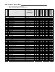
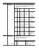
SNVTs1 and SCPTs2 Table Per Model SNVT_temp_p SNVT_temp_p SNVT_temp_p SNVT_lev_percent SNVT_switch SNVT_switch SNVT_occupancy SNVT_hvac_mode SNVT_hvac_mode UNVT_count SNVT_switch SNVT_switch SNVT_temp_p SNVT_temp_p SNVT_lev_percent SNVT_occupancy SNVT_hvac_status UNVT_thermo_state_fc True bit index 2 True bit index 1 True bit index 0 True bit index 7 True bit index 13 True bit index 12 True bit index 15 True bit index 14 True bit index 20 True bit index 21 True bit index 22 True bit index 23 True bit inde
VT7200C5x00E VT7200F5x00E VT7300A5x00E VT7300C5x00E VT7350C5x00E VT7305A5x00E VT7305C5x00E VT7355C5x00E VT7300F5x00E VT7350F5x00E VT7305F5x00E VT7355F5x00E UNVT_cfg_2_fcu_zn X X X X X X X X X X X X Enumeration Set Used: input_cfg_model_a_t Enumeration Set Used: input_cfg_model_b_t Enumeration Set Used: input_cfg_model_c_t Enumeration Set Used: off_on_state_t SNVT_lev_percent SNVT_lev_percent SNVT_lev_percent SNVT_lev_percent UNVT_model_info_2 x x x x x x x x x x x x x
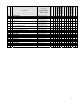
3 4 5 floating_actuator_time cycles_per_hour reverse_or_direct_acting_output 6 menu_scroll 7 auto_mode x x x x x N/A N/A x x x VT7355F5x00E Unsigned-Long Enumeration Set Used: clrl_type_t Unsigned-Short Unsigned-Short Enumeration Set Used: da_ra_type_t Enumeration Set Used: scroll_type_t Enumeration Set Used: VT7305F5x00E X VT7350F5x00E X VT7300F5x00E X VT7355C5x00E X VT7305C5x00E VT7350C5x00E X VT7305A5x00E VT7300C5x00E VT7200F5x00E Sub No 21 nciCfg1FcuZn Associate with UNVT_cfg1
Input Network Variables (nvi’s) Description Parameter Room Temperature Variable Name network input SNVT_temp_p nviSpaceTemp Outdoor Air Temperature network input SNVT_temp_p nviOutdoorTemp Occupied Cool & Heat Setpoints network Input SNVT_temp_p nviSetpoint Room Humidity network input SNVT_lev_percent nviSpaceRH Function This input network variable provides a network remote temperature value to the thermostat.
Parameter Fan Mode Variable Name network input SNVT_switch nviFanSpeedCmd Function This input network variable is used to connect an external fan speed switch to the node or to allow any supervisory device to override the fan speed controlled by the node’s control algorithm. This input is used in conjunction with FanMenu bit in nciGenOpts.
Parameter Occupancy Command Variable Name network input SNVT_occupancy nviOccManCmd Function This input network variable is used to command the Space Comfort Controller into different occupancy modes. It is typically set by a supervisory node to remotely control the occupancy modes to override the local occupancy routines of the thermostat.
Parameter Sequence of operation Variable Name network input SNVT_hvac_mode nviHeatCool1 See note 1 below Remote Lockout network input SNVT_count nviRemLockout Dehumidificati on Lockout network input SNVT_switch nviDhumiLCK Auxiliary Contact Remote Control network input SNVT_switch nviAuxOut Function This network variable input is used to coordinate the Space Comfort Controller with any node that may need to control the heat/cool changeover of the unit.
Output Network Variables (nvo’s) Description All output network variables will be updated no faster than the Minimum Send Time (nciMinOutTm) configuration value. An output network variable will be transmitted immediately when its value has changed significantly (manufacturer’s defined). Additionally, this variable will also be transmitted as a heartbeat output on a regular basis as dictated by the Maximum Send Time (nciSndHrtBt) configuration value.
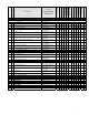
Parameter Unit Status network output Variable Name SNVT_hvac_status nvoUnitStatus Function Sub Name 02: 03 04 05 06 07 Thermostat’s I/O status network output UNVT_thermo_ state_fc nvoSccStatus Heating/ Cooling demand network output SNVT_lev_percent nvoTerminalLoad heat_output _primary heat_output _secondary cool_output: econ_output fan_output In_alarm Valid Value HVAC_FAN_ONLY – Not Used HVAC_MAX_HEAT – Not Used 0-100%, 0x7FFF (Invalid) Not Used 0-100%, 0x7FFF (Invalid) Not Used 0-100%, 0x7FFF (In
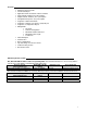
Configuration Properties (nci’s) Description Parameter Temperature Setpoints Variable Name network input config SNVT_temp_setpt nciSetPts RH Model Options network input config UNVT_cfg_2_fcu_zn NciCfg2FcuZn Function This configuration property defines the space temperature setpoints for various heat, cool and occupancy modes. Valid Range and Default values: Sub Name Valid Range Default value 01 occupied_cool 54 to 100°F 75°F (24.0°C) (12 to 37.5°C) 02 standby_cool 54 to 100°F 78°F (25.5°C) (12 to 37.
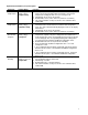
Parameter Thermostat Common Configuration Parameters Variable Name network input config UNVT_cfg_1_fcu_zn nciCfg1FcuZn Function This configuration property defines the thermostat’s common configuration parameters and their settings. Valid Range and Default values: Sub Name Valid Range Default value 01 password 0 to 1000 0 02 control type 0 = On/Off Control 0 = On/Off 1 = Floating Control Control 03 floating actuator time 0.5 to 9 minutes (0.5 1.
Parameter Thermostat Common Configuration Parameters Variable Name network input config UNVT_cfg_1_fcu_zn nciCfg1FcuZn Function This configuration property defines the thermostat’s common configuration parameters and their settings.
Parameter Thermostat’s model number Variable Name network input config UNVT_model_info_2 nciSccModel HVAC UnitType Identifier network input config SNVT_hvac_type nciHvacType Maximum Send Time network input config SNVT_time_sec nciSendHrtBt Minimum Send Time network input config SNVT_time_sec nciMinOutTm Minimum Receive Time network input config SNVT_time_sec nciRcvHrtBt Hardware or Software revisions Hardware or Software revisions network input config SCPT_maj_ver nciMajVer network input config S
Note 1: How to use nviHeatCool, nviAuxHeatEnable and SeqOpera (Sequence of Operation) variables: Current nviHeatCool 3 = HVAC_COOL 3 = HVAC_COOL 1 = HVAC_HEAT 1 = HVAC_HEAT NviAuxHeat Enable = Enabled X X X X X 3 = HVAC_COOL 3 = HVAC_COOL X X 0 = HVAC_AUTO X 2 Pipe Application 0 = Cooling Only 2 = Cooling & Reheat 1 = Heating Only 3 = Heating & Reheat 4 Pipe Application 0 = Cooling Only 1 = Heating Only 3 = Heating & Reheat X 0 = HVAC_AUTO Current SeqOpera 2 = Cooling & Reheat X 1 = HVAC_HEAT
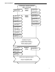
Integration – Global Commands The following figure shows, which objects from the thermostat, can be monitored and commanded from the BAS front-end.
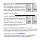
VT7200X Integration – Graphic User Interface (GUI) objects The following objects should be typically used in a GUI: nvoSpaceTemp; occupied_heat (nciSetpts); unoccupied_heat (nciSetpts); occupied_cool (nciSetpts); unoccupied_cool (nciSetpts); nvoOutdoorTemp nvoDischAirTemp nvoEffectOccup; heat_output_primary (nvoUnitStatus) cool_output (nvoUnitStatus) nvoTerminalLoad ServiceAlarm (nvoSccStatus) FilterAlarm (nvoSccStatus) WindowOpened (nvoSccStatus) Graphical User Interface (GUI) example of a zoning thermost
VT73xxX Integration – Graphic User Interface (GUI) objects The following objects should be typically used in a GUI: nvoSpaceTemp occupied_heat (nciSetpts); unoccupied_heat (nciSetpts); occupied_cool (nciSetpts); unoccupied_cool (nciSetpts); nvoSpaceRH RHsetpoint (nciRHmodel); nvoOutdoorTemp nvoDischAirTemp nviOccManCmd nvoEffectOccup heat_output_primary (nvoUnitStatus) cool_output (nvoUnitStatus) ServiceAlarm (nvoSccStatus) FilterAlarm (nvoSccStatus) WindowOpened (nvoSccStatus) Graphical User Interface (GU
Configuration Property Objects The following SNVT and UNVT should be typically used for configuration purposes: nciCfg1FcuZn; nciCfg2FcuZn; nciSetpoints; Wiring Guide Overview For clarity we will use the term “Device” to represent any product with an active Echelon network connection, including Viconics and non-Viconics controllers.
Maximum Number Of Devices Up to 64 transceivers are allowed per network segment.
Maximum Cable Length The maximum length of a chain is related to its transmission speed. The longer the chain, the slower the speed. Using proper cable, Echelon supports a baud rate of 78 kilobits per second for distances up to 1600ft (500 m) in free topology and 8800 ft (2700 m) in bus topology with double terminations. If you require a maximum network length of more than 1600-ft (500 m) or 8800 ft (2700 m), then a repeater is required to extend the network.
Network adapter Although network connections are polarity insensitive, it is good practice to keep polarity consistent throughout the entire site. Figure 4 shows a network connection example and the location of the Status LED. This Status LED may help to troubleshoot network problems. Figure 4: Network connections and location of the Status LED on a LON module Table 2 shows the different possibilities with the Status LED behaviour of the LON module.
Device Identification An Echelon device has a unique mechanism to identify itself, the Neuron ID, which is obtained during commissioning. There are two ways of getting the Neuron ID: with a Service Pin or manually. Service PIN The service pin is used to identify the device at commissioning.
Manual Identification Neuron ID of a device can also be entered manually through a commissioning or service tool. Neuron ID should be located on the Echelon chip of the device being commissioned. Figure 8 shows an example of a Manual Neuron ID request made through a commissioning tool.