PIR Ready VT7300F5X00B-2572 24 VAC Low Voltage ECM Fan Coil Terminal Equipment Controller Installation Guide For Commercial and Lodging FCU Applications rd May 3 , 2012 / 028-0381-R4 CONTENTS Installation Location Installation Features overview Configurable BI/UI inputs overview Model Selection Terminal, Identification and Function Wiring Screw terminal arrangement Main outputs wiring Remote sensor accessories Configuring and Status Display Instructions Status display User Interface Local keypad interface
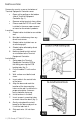
I NSTALLATION Remove the security screw on the bottom of Terminal Equipment Controller cover. Open unit by pulling on the bottom side of Terminal Equipment Controller (fig. 1). Remove wiring terminals from sticker. Please read the FCC ID and IC label installed in the cover upon removal of cover for the wireless products. Location 1. Should not be installed on an outside wall. 2. Must be installed away from any direct heat source. 3. Should not be installed near an air discharge grill. 4.
10. Insert each wire according to wiring diagram. 11. Gently push excess wiring back into hole (fig. 3). 12. Re-Install wiring terminals in their correct locations (fig. 3). 13. Re-install the cover (top side first) and gently push extra wire length back into the hole in the wall. 14. Install security screw. When replacing an existing Terminal Equipment Controller, label the wires before removal of the Terminal Equipment Controller. Electronic controls are static sensitive devices.
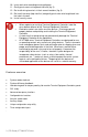
CONFIGURABLE BI/UI INPUTS OVERVIEW Binary input #1 can be configured for the following functions: 1. (None): No function will be associated with the input 2. (Rem NSB): remote NSB timer clock input. The scheduling will now be set as per the binary input. It provides low cost setback operation via a dry contact Contact opened = Occupied Contact closed = Unoccupied 3. (Motion NO) and (Motion NC): Advanced PIR occupancy functions using a normally open (NO) or normally closed (NC) remote PIR motion sensor.
Contact closed = Alarm displayed 5. (Service): a backlit flashing Service alarm will be displayed on the Terminal Equipment Controller LCD screen when the input is energized. It can be tied in to the AC unit control card, which provides an alarm in case of malfunction. Contact opened = No alarm Contact closed = Alarm displayed Universal input #3 can be configured for the following functions: 1. (None): No function will be associated with the input 2. (COC/NH) Change over dry contact.
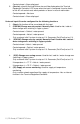
MODEL S ELECTION Part number Description Communication Options VT7300F5X00-2572 Commercial Applications with Override Communication Ready VT7300F5X00B-2572 Commercial Applications with Override BACnet MS/TP VT7305F5X00-2572 °C/°F Hotel/Lodging Applications Communication Ready VT7305F5X00B-2572 °C/°F Hotel/Lodging Applications BACnet MS/TP - Controllers can be ordered with a factory installed PIR cover. Please use (5500) extension instead of the (5000) only extension. Ex. VT7300F5500B-2572.
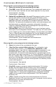
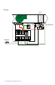
Wiring Hot/Cold Water Coil FAN 24 Vac On/ 2-10 Off Vdc 24Vac Transformer Water Supply Sensor (Valve Open Position Detector) NO contact 0-10 Vdc Bi1 Ui3 24V-Com 12 7 Bi2 24V-Hot AO1 10 6 BO5 Fan-L AO2 9 7 | PIR Ready VT7300-2572 Series 5 Scom Fan-M 4 RS 3 BO5 2 Fan-H Water Detector (NO contact) 1 13 14 15 16 24 Vac
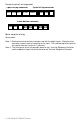
Screw terminal arrangement 3 pole left top connector 5 pole left top connector Fan H Fan M Fan L 24V~Hot 24V-Com BO5 BO5 8 pole bottom connector AO2 AO1 BI1 RS Scom BI2 UI3 Main outputs wiring Wiring notes: Note 1: Electromechanical contacts are to be used with the digital inputs. Electronic triacs cannot be used as mean of switching for the input. The switched leg to the input for the input to activate is terminal C (common).
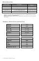
Remote sensor accessories Model no. S3010W1000 S3020W1000 S2060A1000 S2000D1000 Description Wall mounted temperature sensor Wall mounted temperature sensor with override button and occupancy status LED Averaging temperature sensor Duct mounted temperature sensor S3020W1000 WALL MOUNTED SENSOR Remote mount temperature sensors use 10K type 2 NTC thermistors.
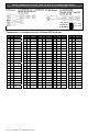
Wiring examples of 3 remote room sensors for averaging applications: Dip switch setting for: 3 sensors ON 1 S2-1 = OFF 2 S2-2 = OFF Temperature vs. resistance chart for 10 Kohm NTC thermistor ºC ºF Kohm ºC ºF Kohm ºC ºF Kohm ºC ºF Kohm ºC ºF Kohm -40 -40 324.3197 -20 -4 94.5149 0 32 32.1910 20 68 12.4601 40 104 5.3467 -39 -38 303.6427 -19 -2 89.2521 1 34 30.6120 21 70 11.9177 41 106 5.1373 -38 -36 284.4189 -18 0 84.3147 2 36 29.1197 22 72 11.4018 42 108 4.
CONFIGURING AND STATUS DISPLAY INSTRUCTIONS Status display The Terminal Equipment Controller features a two-line, eight-character display. There is a low level backlight that is always active and can only be seen at night. When left unattended, the Terminal Equipment Controller has an auto scrolling display that shows the current status of the system. Each item is scrolled sequentially with the back lighting in low level mode. Pressing any key will cause the back light to come on to high level.
Three status LED’s on the Terminal Equipment Controller cover are used to indicate the status of the fan (any speed), a call for heat, or a call for cooling. Fan coil models When the fan is ON, the FAN LED will illuminate When heating & reheat is ON, the HEAT LED will illuminate When cooling is ON, the COOL LED will illuminate USER INTERFACE Unoccupied mode override An Override can be made on commercial models during an unoccupied period.
Local keypad interface Each of the sections in the menu is accessed and configured using 5 keys on the Terminal Equipment Controller cover. Is used to toggle between the different system modes available as per sequence and menu selected. Repetitively pressing the button will toggle between all the available modes. Available menus are dependent on selected sequence of operation.
Single occupied setpoints adjustment (Local occupied setpoint adjustment when “Stp Func” = Attch Stp ) AUTO MODE COOLING MODE HEATING MODE OFF MODE Cool XX.X °F or °C Heat XX.X °F or °C No access to setpoint Setpoint presented to user is the setpoint from the last action taken by the Terminal Equipment Controller or the one currently in use.
Available fan button menu sequences 0 Low-Med-High Default value Menu presented are dependent on model used when sequence and sequence of operation selected toggled 3 Speed configuration (2.0Vdc, 6.0Vdc, 10.0Vdc) High 1 Low-High 2 Speed configuration (2.0Vdc, 10.0Vdc) High 2 Low-Med-High-Auto 3 Speed configuration with Auto fan speed mode (2.0Vdc, 6.0Vdc, 10.0Vdc or modulating 2.0 to High AO2 Parameter ) High 3 Low-High-Auto 2 Speed configuration with Auto fan speed mode (2.0Vdc,10.
CONFIGURATION PARAMETERS DEFAULT VALUE PswrdSet Configuration parameters menu access password Default value = 0 Range is: 0 to 1000 SIGNIFICANCE AND ADJUSTMENTS This parameter sets a password access to prevent unauthorized access to the configuration menu parameters. A default value of “0” will not prompt a password or lock the access to the configuration menu.
BI 2 Binary input no.2 configuration (None): No function will be associated with the input (Door Dry) Door contact & Motion detector: This Default value = None configuration is only functional if binary input #1 is set to Motion NO or Motion NC or a PIR accessory cover is used. With this sequence enabled, the occupancy is now dictated through those 2 inputs. Any motion detected will set the zone to occupied status.
UI3 Universal input no.3 configuration Default value = None (None): No function will be associated with the input (COC/NH) Change over dry contact. Normally Heat: Used for hot / cold water or air change over switching in 2 pipe systems. Contact closed = Cold water or air present Contact opened = Hot water or air present Only used and valid if system is setup as 2 pipes. Parameter (Pipe No) set as 2 pipes. (COC/NC) Change over dry contact.
Lockout Keypad lockout levels Default value = 0 No lock USER KEY FUNCTIONS LEVEL 0 1 2 3 4 5 SeqOpera Sequence of operation Selects the initial sequence of operation required by the installation type and the application Default is: Sequence #1 SEQUENCE OF OPERATION SYSTEM = 2 PIPES SYSTEM = 4 PIPES 0 = Cooling Only Off - Cool 0 = Cooling Only 1 = Heating Only Off - Heat 1 = Heating Only 2 = Cooling With Electric Reheat 3 = Heating With Electric Reheat Off – Auto – Heat – Cool 2 = Cooling With
St-By TM Stand-by Timer value Default = 0.5 hours Time delay between the moment when the PIR sensor detected the last movement in the area and the time when the Terminal Equipment Controller stand-by mode and setpoints become active. Range is: 0.5 to 24.0 hours in 0.5hr increments Unocc TM Unoccupied Timer value Default = 0.
Cool min Minimum occupied & unoccupied cooling setpoint Minimum cooling setpoint limit adjustment. Default value = 54 °F ( 12 °C ) Cooling setpoint range is: 54 to 100 °F ( 12.0 to 37.5 °C ) Pband Proportional band setting Default = 3 Adjust the proportional band used by the Terminal Equipment Controller PI control loop. Note that the default value of 3.0 °F ( 1.2 °C ) gives satisfactory operation in most normal installation cases.
Set Type Temporary setpoint enable Default is : Permnent Enables temporary setpoints feature to any change of occupied or unoccupied setpoint. Temporar: (temporary) Local changes to the heating or cooling setpoints by the user are temporary. They will remain effective for the duration specified by “ToccTime”. Setpoints will then revert back to their default value after internal timer “ToccTime” expires. To change setpoints permanently, revert this variable to No or write setpoints through the network.
aux cont Auxiliary contact function & configuration Default value = 0 Not Used 0 Aux contact function used for reheat IF SEQUENCE IS SET TO REHEAT THROUGH NETWORK OR LOCAL, Ignore this parameter.
Med AO2 Default value: 6.0 V The middle speed AO2 fan output value when the fan is enabled. This value is used only if the fan mode is set to Med. 4.1 to 7.0 V High AO2 The maximum AO2 fan output value when the fan is enabled. Default value: 8.6 V This value is used if the fan mode is set to High and as a maximum output if the fan output is set to auto. 7.1 to 10.0 V UI3 dis Used as diagnostic / service help to troubleshoot and diagnose Display UI3 value.
S PECIFICATIONS Terminal Equipment Controller power requirements: Operating conditions: Storage conditions: Temperature sensor: Temperate sensor resolution: Temperature control accuracy: Contact output rating Occ, Stand-By and Unocc cooling setpoint range: Occ, Stand-By and Unocc heating setpoint range: Room and outdoor air temperature display range: Proportional band for room temperature control: Binary inputs: Wire gauge: Approximate shipping weight: Agency Approvals all models: Agency Approvals all mod
DRAWING & DIMENSIONS Viconics Technologies Inc. Tel.: 26 | PIR Ready VT7300-2572 Series Fax: Toll free: www.viconics.