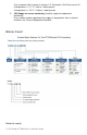
PIR Ready VT7300 Series 24 V AC Low V olt ag e Fan Co il T e rmi na l Equ ip men t T e rm in al Equ ip men t Cont ro ll e r Installation Guide For Commercial and Lodging HVAC F a n C o i l Ap p l i c a t i o n s June 8th, 2012 / 028-0183 R8 CONTENTS Installation Location Installation Configurable BI/UI inputs overview Model Chart Network ready Terminal, Identification and Function Terminal identification Wiring Main outputs wiring Typical applications Remote sensor accessories Status display User Interfac
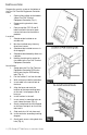
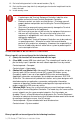
I NSTALLATION Remove the security screw on the bottom of the Fan Coil Terminal Equipment Controller cover. Open unit by pulling on the bottom side of Fan Coil Terminal Equipment Controller (Fig. 1). Remove wiring terminals from sticker. Please read the FCC ID and IC label installed in the cover upon removal of cover for the wireless products. Location 1. Should not be installed on an outside wall. 2. Must be installed away from any direct heat source. 3.
12. Re-Install wiring terminals in their correct locations (Fig. 3). 13. Re-install the cover (top side first) and gently push extra wire length back into the hole in the wall. 14. Install security screw. If replacing an old Terminal Equipment Controller, label the wires before removal of the old Terminal Equipment Controller. Electronic controls are static sensitive devices. Discharge yourself properly before manipulation and installing the Terminal Equipment Controller.
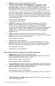
1. (None): No function will be associated with the input 2. (Door Dry) Door contact & Motion detector: This configuration is only functional if binary input #1 is set to Motion NO or Motion NC or a PIR accessory cover is used. With this sequence enabled, the occupancy is now dictated through those 2 inputs. Any motion detected will set the zone to occupied status. The zone will remain permanently in occupied mode until the door contact switch opens momentarily.
Only used and valid if system is setup as 2.0. Parameter ( Out1Conf ) set as 2.0. If temperature is > 77 °F = Hot air / water present If temperature is < 75 °F = Cold air / water present 5. (SS) Supply air sensor monitoring: Used for supply air temperature monitoring. Only used for network reporting of the supply air temperature. Has no internal function in the Terminal Equipment Controller.
All Viconics VT7300 series Terminal Equipment Controllers are designed for stand-alone (Network Ready) operation. They can be fully integrated into your choice of automation systems using the available communication adapter options.
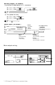
Auxiliary output ( All models ) - Dry contact to end device 24 V~ maximum #4 24 V~ Hot #5 24 V~ Com #6 #7 R - 24 VAC power to relay #4 24 V~ Hot #5 24 V~ Com #6 #7 R Remote inputs ( All models ) BI 1 Remote wall sensor RS - S3010W1000 - S3020W1000 Scom BI 2 UI 3 Contact - Rem NSB - Motion - Window Contact - Door - Remote Override - Filter alarm - service alarm SS ( supply sensor ) - S1010E1000 - S2000D1000 COS ( changeover sensor ) - S1010E1000 OR COC/NH - Normally heat - Closed contact = cold water C
Floating control VT7300C5x00(x), VT7305C5x00(x), VT7350C5x00(x) & VT7355C5x00(x) 24 V~ Hot 24 V~ Com 24 V~ Hot 24 V~ Com BO3 BO4 BO1 BO2 Heating / Cooling valve BO1 BO2 Open Com Close Open Com Close Heating valve Open Com Close Cooling valve Analog control VT7300F5x00(x), VT7305F5x00(x), VT7350F5x00(x) & VT7355F5x00(x) 24 V~ Hot 24 V~ Com 24 V~ Hot 24 V~ Com Heating / Cooling valve AO 2 Com 24 VAC 0-10 VDC AO 1 AO 1 Com 24 VAC 0-10 VDC Heating valve Com 24 VAC 0-10 VDC Cooling valve Typica
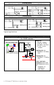
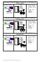
2 pipe system cooling and/or heating: VT7300C5x00(x) & VT7305C5x00(x) Floating actuator 24 VAC fan relays Modulating Floating Valve Cooling and/or Heating High Fan-H Fan-M 3 Speed fan Med Fan-L Low UI3 COS 24 V~ Com 24 V~ Hot If cooling only set:: SeqOpera = 0 Cooling only BO1 Open Room Temperature Control Thermostat Mandatory Pipe no = 2 pipes CntrltTyp = Floating Fan Menu = 0 (L-M-H) FL time = as per actuator BO2 Close Optional supply water temperature sensor If heating only set::
4 pipe system cooling and heating: VT7300C5x00(x) & VT7305C5x00(x) On / Off N.C.
2 pipe system cooling or heating with reheat: VT7300C5x00(x) & VT7305C5x00(x) Floating actuator Modulating Floating Valve Cooling and/or Heating BO5 BO5 Fan-H Fan-M 3 Speed fan Fan-L Electric Reheat UI3 COS High Med Low 24 VAC fan relays 24 V~ Com 24 V~ Hot BO1 Open Room Temperature Control Thermostat BO2 Close Mandatory Pipe no = 2 pipes CntrltTyp = Floating Fan Menu = 0 (L-MH) FL time = as per actuator SeqOpera = 2 Cool/Reheat UI3 = COS Optional supply water temperature sensor Remo
Wiring examples of 2 remote room sensors for averaging applications: Notes for averaging applications: S3010W1000 and S3020W1000 can be mixed matched. S3010W1000 and S3020W1000 are to be wired in parallel. Respect the dip switch setting in each remote sensor.
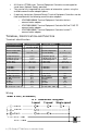
Temperature vs. resistance chart for 10 Kohm NTC thermistor (R25°C = 10K±3%, B25/85°C = 3975K±1.5%) ºC ºF 40 35 30 25 Kohm ºC ºF Kohm ºC ºF Kohm ºC ºF Kohm ºC ºF Koh m -40 324.3197 -20 -4 94.5149 0 32 32.1910 20 68 12.4601 40 104 5.3467 -31 234.4009 -15 5 71.2430 5 41 25.1119 25 77 10.0000 45 113 4.3881 -22 171.3474 -10 14 54.1988 10 50 19.7390 30 86 8.0694 50 122 3.6202 -13 126.6109 -5 23 41.5956 15 59 15.6286 35 95 6.5499 55 131 3.
Occupied, Stand-By, Unoccupied and Override status are displayed on the scrolling display. Alarms If alarms are detected, they will automatically be displayed at the end of the scrolling status display. When an alarm message is displayed, the backlit screen will illuminate at the same time as the message and shut off during the rest of the status display. A maximum of two alarms can appear at any given time.
An Override can be made on commercial models during an unoccupied period. If the Override option is enabled in the lockout configuration, pressing the middle override button will resume occupied setpoints for a time specified by the parameter “ToccTime”.
Local keypad interface Is used to toggle between the different system modes available as per sequence and menu selected. Repetitively pressing the button will toggle between all the available modes. Available menus are dependent on selected sequence of operation.
Single occupied setpoints adjustment (Local occupied setpoint adjustment when “Stp Func” = Attch Stp ) AUTO MODE COOLING MODE OFF MODE HEATING MODE Cool XX.X °F or °C Heat XX.X °F or °C No access to setpoint Setpoint presented to user is the setpoint from the last action taken by the Terminal Equipment Controller or the one currently in use.
Available fan button menu sequences FAN BUTTON MENU CONFIGURATION MENU PRESENTED ARE DEPENDENT ON MODEL USED AND SEQUENCE OF OPERATION SELECTED DEFAULT VALUE WHEN SEQUENCE TOGGLED 0 Low-Med-High 3 Speed configuration using 3 fan relays ( L-M-H ) High 1 Low-High 2 Speed configuration using 2 fan relays ( L-H ) High 2 Low-MedHigh-Auto 3 Speed configuration with Auto fan speed mode using 3 fan relays ( L-M-H-A ) High 3 Low-High-Auto 2 Speed configuration with Auto fan speed mode using 2 fan relays (
Configuration interface Re-starts the configuration parameter list from the beginning Enters the configuration mode.
PAN ID Personal Area Network Identification Default value = 0 Range is: 0 to 500 Conditional parameter to Wireless models VT73xxX5x00W This parameter will only appear when a wireless network adapter is present. If the Terminal Equipment Controller is installed as a stand-alone (Network Ready) unit or with a BACnet™ or Echelon™ adapter, this parameter will not be used or displayed.
Get From Terminal Equipment Controller Get From another device configuration utility Default value = 0 Range is: 0 to 254 Conditional parameter to Wireless models VT73xxX5x00W Entering a MAC address enables an automatic routine that automatically fetches all the required configuration properties of the current device from another already configured device and copies the same required configured property values.
BI 1 Binary input no.1 configuration Default value = None (None): No function will be associated with the input. Input can be used for remote network monitoring. (Rem NSB): remote NSB timer clock input. The scheduling will now be set as per the binary input. It provides low cost setback operation via a dry contact Contact opened = Occupied Contact closed = Unoccupied (Motion NO) or (Motion NC): Advanced PIR occupancy functions using a Normally Open (NO) or Normally Closed (NC) remote PIR motion sensor.
BI 2 Binary input no.2 configuration Default value = None (None): No function will be associated with the input (Door Dry) Door contact & Motion detector: This configuration is only functional if binary input #1 is set to Motion NO or Motion NC or a PIR accessory cover is used. With this sequence enabled, the occupancy is now dictated through those 2 inputs. Any motion detected will set the zone to occupied status.
UI3 Universal input no.3 configuration Default value = None (None): No function will be associated with the input (COC/NH) Change over dry contact. Normally Heat: Used for hot / cold water or air change over switching in 2 pipe systems. Contact closed = Cold water or air present Contact opened = Hot water or air present Only used and valid if system is setup as 2 pipes. Parameter (Pipe No) set as 2 pipes. (COC/NC) Change over dry contact.
%RH disp Local %RH Display Default value = Off Models with Humidity sensor only Conditional parameter to Humidity models VT735xX5x00(X) Enables the display of humidity value below the room temperature value on the display On = Display %RH Off = No display of %RH Lockout Keypad lockout levels Default value = 0 No lock USER KEY FUNCTIONS LEVE L 0 1 2 3 4 5 Pipe No System type installation Number of pipes Default is: 4.0 Pipes Defines the type of system installed 2.
SYSTEM = 2 PIPES SYSTEM = 4 PIPES 0 = Cooling Only Off - Cool 0 = Cooling Only 1 = Heating Only Off - Heat 1 = Heating Only 2 = Cooling With Electric Reheat 3 = Heating With Electric Reheat Off – Auto – Heat – Cool 2 = Cooling With Electric Reheat 3 = Heating With Electric Reheat 4 = Cooling and Heating (2 modulating outputs) 5 = Cooling / Heating (2 modulating outputs) with reheat Off – Auto – Heat – Cool Off - Heat 4 = Cooling and Heating (2 modulating outputs) Off – Auto – Heat – Cool 5 = C
DehuHyst Dehumidification Hysteresys Default = 5 % RH Conditional parameter to Humidity models VT735xX5x00(X) Humidity control hysteresis. Used only if dehumidification sequence is enabled: Range is: 2 to 20% RH DehuCool Maximum Dehumidification Cooling output Default = 100 % Conditional parameter to Humidity models VT735xX5x00(X) Maximum cooling valve position when dehumidification is enabled. This can be used to balance smaller reheat loads installed relative to the capacity of the cooling coil.
Unocc CL Unoccupied cooling setpoint limit Default value = 80 °F Unoccupied cooling setpoint range is: 54 to 100 °F ( 12.0 to 37.5 °C ) Heat max Maximum heating setpoint limit Default value = 90 °F ( 32 °C ) Maximum occupied & unoccupied heating setpoint adjustment. Heating setpoint range is: 40 to 90 °F ( 4.5 to 32.0 °C ) Cool min Minimum occupied & unoccupied cooling setpoint Minimum cooling setpoint adjustment. limit Default value = Cooling setpoint range is: 54 to 100 °F ( 12.0 to 37.
Set Type Temporary setpoint enable Default is : Permnent Temporar: (temporary) Local changes to the heating or cooling setpoints by the user are temporary. They will remain effective for the duration specified by “ToccTime”. Setpoints will then revert back to their default value after internal timer “ToccTime” expires. Enables temporary setpoints feature to any To change setpoints permanently, revert this variable to No change of occupied or or write setpoints through the network.
aux cont Auxiliary contact function & configuration Default value = 0 Not Used 0 Aux contact function used for reheat IF SEQUENCE IS SET TO REHEAT THROUGH NETWORK OR LOCAL, Ignore this parameter.
Reheat Sets the reheat output time base Default value: 0 = 15 Valid only if reheat sequences are enabled minute 0 = 15 minutes 1 = 10 seconds for Solid state relays UI3 dis Used as diagnostic / service help to troubleshoot and Display UI3 value.
S PECIFICATIONS Terminal Equipment Controller power requirements: Operating conditions: Storage conditions: Temperature sensor: Temperate sensor resolution: Temperature control accuracy: Humidity sensor and calibration Humidity sensor precision Humidity sensor stability Dehumidification setpoint range Contact output rating Occ, Stand-By and Unocc cooling setpoint range: Occ, Stand-By and Unocc heating setpoint range: Room and outdoor air temperature display range: Proportional band for room temperature co
DRAWING & DIMENSIONS Viconics Technologies Inc. Tel.: Fax: Toll free: www.viconics.