PIR Ready VT7600 Series Programmable & Non-Programmable Thermostats For Commercial HVAC Applications LonWorks Integration Manual ITG-VT7600-PIR-LON-E05 (028-6005 R5 - Issue Date: June 4, 2009) 1
Product Overview The VT7600 PI thermostat family is specifically designed for single stage and multi-stage control of heating/cooling equipment such as rooftop and selfcontained units. The product features an intuitive, menu-driven, back-lit LCD display, which walks users through the programming steps, making the process extremely simple.
PID History Revision Table XIF, APB and NXE File Names and Corresponding PIDs. This manual information is to be used only with the current released VT7600 PIR ready thermostats. Used on current APB / NXE / XIF file Revision Level Associated PID released thermostat names PIR Ready VT7600 Series VT76_PIR.XIF Rev 3.0 80:00:C5:55:00:04:04:21 This manual information is NOT to be used only with the previously released VT7600 thermostats.
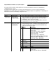
18 keypad_lockout 19 20 proportional_band temperature_units 21 frost_protection 22 menu_scroll VT7600H5x00E fan_delay VT7652H5x00E 17 Unsigned-Long Unsigned-Short Unsigned-Short Unsigned-Short Unsigned-Short Unsigned-Short Unsigned-Short SNVT_temp_p SNVT_temp_p SNVT_temp_p SNVT_temp_p SNVT_temp_diff_p SNVT_temp_diff_p Unsigned-Short Enumeration Set Used: fan_mode_b-t Enumeration Set Used: off_on_state_t Enumeration Set Used: off_on_state_t Enumeration Set Used: rem_lock_t Unsigned-Short Enumerat
progresive_recovery 6 a.hp_rev_valve_config 7 a.number_of_heating_stages 8 number_of_cool_or_hp_stages 9 10 11 12 13 14 econo_min_position b.hp_high_balance_point b.econo_changeover_setpoint c.hp_low_balance_point c.econo_mixed_air_setpoint d.hp_comfort_or_economy_mode 15 d.
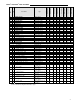
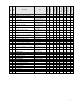
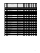
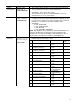
VT7605B5x00E VT7652B5x00E VT7600B5x00E VT7652A5x00E VT7600A5x00E VT7652H5x00E VT7600H5x00E nvoSccStatus Type VT7656B5x00E Sub No 22 Point Name UNVT_thermo_state_rtu UNVT_thermo_state_hp X X X X X X X X x x x x x x x x x x x x x x x x x x x x x x x N/A x x x x x x x x x x x x x x x x x x x x x x x x x N/A x x x x N/A x x x x x x x x x x x x N/A x x x x x x x N/A x x x x x x x x x x x x x x x x x x x x x x x x x N/A x x x x x x x x x x x x x x x x x x x x x x x x x N/A x x x x
Input Network Variables (nvi’s) Description Parameter Room Temperature Variable Name network input SNVT_temp_p nviSpaceTemp Outdoor Air Temperature network input SNVT_temp_p nviOutdoorTemp Occupancy network input SNVT_occupancy nviOccManCmd Function This input network variable provides a network remote temperature value to the thermostat. If a valid value is present, the internal temperature reading (internal sensor) is no longer used.
Parameter Occupied Cool & Heat Setpoints Variable Name network Input SNVT_temp_p nviSetpoint Date and time network input SNVT_time_stamp nviTimeSet Function This input network variable is used to allow the occupied temperature setpoints only to be changed via the network from a single analog value. (Note: the Unoccupied setpoints are not changed). The corresponding heating and cooling values are derived from the minimum deadband configuration value Default Null Value: 621.81°F (327.67°C or 0x7FFF) Ex.
Output Network Variables (nvo’s) Description All output network variables will be updated no faster than the Minimum Send Time (nciMinOutTm) configuration value, if used. An output network variable will be transmitted immediately when its value has changed significantly. Additionally, this variable will also be transmitted as a heartbeat output on a regular basis as dictated by the Maximum Send Time (nciSndHrtBt) configuration value.
Parameter Supply Temperature Variable Name network output SNVT_temp_p nvoDischAirTemp Occupancy network output SNVT_occupancy nvoEffectOccup Thermostat’s I/O status network output UNVT_thermo_state_rtu UNVT_thermo_state_hp nvoSccStatus Function This output network variable is used to monitor the temperature of the air that leaves the Space Comfort Controller Valid Range: -40 to 122°F (-40 to 50°C) The value 621.81°F (327.67°C or 0x7FFF)will be sent as an invalid value in case of a sensor failure.
Parameter Setpoint Variable Name network output SNVT_temp_p nvoEffectSetpt Local setpoint network output output SNVT_temp_p nvoSetPoint Function This output network variable is used to monitor the effective temperature setpoint which may depend on nciSetpoints, nvoEffectOccup, nviSetpoint and any local setpoint adjustment. For example, if the occupancy state is unoccupied and the heat/cool state is heat, the effective setpoint would be equal to the unoccupied heating setpoint defined in nciSetpoints.
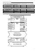
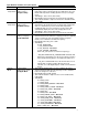
Parameter Variable Name Thermostat’s UNVT_cfg_1_rtu_hp common nciCfg1RtuHpt configuration parameters network input config Function This configuration property defines the thermostat’s common configuration parameters and their settings. Valid Range and Default values: Name Valid Range Default value password 0 to 1000 0 unoccupied timer 0.5 to 24.0 hours 0.5 anticycle 0, 1, 2, 3, 4, or 5 minutes 2 minutes power-up delay 10 to 120 sec. 10 sec.
Parameter Variable Name UNVT_cfg_2_rtu_hp Thermostat’s nciCfg2RtuHpt common configuration parameters network input config Function Name di1 config di2 config aux contact config number of events progressive recovery a.
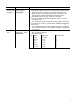
Parameter Variable Name Thermostat’s network input config model number UNVT_model_info_2 nciSccModel Maximum Send Time network input config SNVT_time_sec nciSendHrtBt Minimum Send Time network input config SNVT_time_sec nciMinOutTm Minimum Receive Time network input config SNVT_time_sec nciRcvHrtBt Hardware or Software revisions Hardware or Software revisions Location Label network input config SCPT_maj_ver nciMajVer network input config SCPT_min_ver nciMinVer network input config SNVT_str_asc nciLo
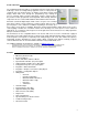
Integration – Global Commands The following figure shows which objects from the thermostat can be monitored and commanded from the BAS front-end.
nviOutdoorTemp Figure 2: Graphical User Interface (GUI) example of a Roof Top Unit 16
Configuration Objects The following SNVT and UNVT should be typically used for configuration purposes: nciCfg1RtuHp; nciSetpoints; nciCfg2RtuHp; nviDaySchedule[0] nviDaySchedule[1] nviDaySchedule[2] nviDaySchedule[3] nviDaySchedule[4] nviDaySchedule[5] nviDaySchedule[6] Wiring Guide Overview For clarity we will use the term “Device” to represent any product with an active Echelon network connection, including Viconics and non-Viconics controllers.
Maximum Number Of Devices Up to 64 transceivers are allowed per network segment.
Maximum Cable Length The maximum length of a chain is related to its transmission speed. Using proper cable, Echelon supports a baud rate of 78 kilobits per second for distances up to 1600-ft (500 m) in free topology and 8800 ft (2700 m) in bus topology with double terminations. If you require a maximum network length of more than 1600-ft (500 m) or 8800 ft (2700 m), then a repeater is required to extend the network.
Network Adapter Although network connections are polarity insensitive, it is good practice to keep polarity consistent throughout the entire site. Figure 4 shows a network connection example and the location of the Status LED. This Status LED may help to troubleshoot network problems. Figure 4: Network connections and location of the Status LED on a LON module Table 2 shows the different possibilities with the Status LED behavior of the LON module.
Device Identification An Echelon device has a unique mechanism to identify itself, the Neuron ID, which is obtained during commissioning. There are two ways of getting the Neuron ID: with a Service Pin or manually. Service PIN The Service PIN is used to identify the device at commissioning.
Manual Identification Neuron ID of a device can also be entered manually through a commissioning or service tool. Neuron ID should be located on the Echelon chip of the device being commissioned. Figure 8 shows an example of a Manual Neuron ID request made through a commissioning tool.