VT7600F Series RTU Terminal Equipment Controller with Modulating Heat Installation Guide For Commercial HVAC Applications th January 30 , 2012 / 028-377-R2 CONTENTS Installation Location Installation Theory of Operation Features overview Model Chart Network ready Terminal, Identification and Function Screw terminal arrangement and wiring Typical Applications Main outputs wiring Remote sensor accessories Configuring and Status Display Instructions Status display User interface User configuring instruction
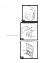
I NSTALLATION Remove the security screw on the bottom of Terminal Equipment Controller cover. Open unit by pulling on the bottom side of Terminal Equipment Controller (fig. 1). Remove wiring terminals from sticker. Please read the FCC ID and IC label installed in the cover upon removal of cover for the wireless products. Location 1. Should not be installed on an outside wall. 2. Must be installed away from any direct heat source. 3. Should not be installed near an air discharge grill. 4.
10. Insert each wire according to wiring diagram. 11. Gently push excess wiring back into hole (fig. 3). 12. Re-Install wiring terminals in their correct locations (fig. 3). 13. Re-install the cover (top side first) and gently push extra wire length back into the hole in the wall. 14. Install security screw. When replacing an existing Terminal Equipment Controller, label the wires before removal of the Terminal Equipment Controller. Electronic controls are static sensitive devices.
Features overview 7 day schedule models, 2 or 4 events. Remote outdoor sensing capability for added flexibility. System mode heating and cooling lockout. Remote discharge air sensor input for monitoring and control purpose. System efficiency feedback. Discharge high limit heating lockout. Discharge low limit cooling lockout. Minimum supply air temperature. Remote return air sensor input that replaces internal on board sensor.
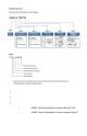
MODEL CHART Network ready All Viconics VT7600 series Terminal Equipment Controllers are designed for stand-alone (Network Ready) operation. They can be fully integrated into your choice of automation systems using the available communication adapter options.
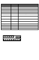
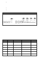
TERMINAL , IDENTIFICATION AND FUNCTION Terminal Identification Terminal Use Description 1 – Y2 2nd cooling Y2 Second cooling stage output. st Y1 First cooling stage output. G Fan output. 4 – RC 24VAC hot RC Power supply of thermostat, hot side. 5 – C 24VAC com 2 – Y1 1 cool 3 – G Fan C Power supply of thermostat, common side. 9 – AO analog heat AO Analog 0 – 10 VDC heating output.
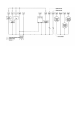
TYPICAL APPLICATIONS Main outputs wiring Wiring notes: Note 1: If the same power source is used for the heating stages, install jumper across RC & RH. Maximum current is 2.0 amps. Note 2: If auxiliary output is used to toggle occupancy of the electronic control card inside the equipment, configure the relay parameter (Aux cont) to the N.O. setting. A second relay can be added for additional functionality of the occupancy output. Note 3: The analog outputs and inputs use a half bridge rectifier.
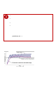
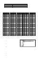
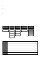
Remote sensor accessories Model no. S2020E1000 S2060A1000 S2000D1000 Description Outdoor temperature sensor Averaging temperature sensor Duct mounted temperature sensor Remote mount temperature sensors use 10K NTC thermistor. Temperature vs. Resistance Chart for 10 Kohm NTC Thermistor ºC ºF Kohm (R25°C = 10K±3% - B25/85°C = 3975K±1.5%) ºC ºF Kohm ºC ºF Kohm ºC ºF Kohm ºC ºF Kohm -40 -40 324.3197 -20 -4 94.5149 0 32 32.1910 20 68 12.4601 40 104 5.3467 -39 -38 303.6427 -19 -2 89.
Supply air temperature averaging sensor for economizer models with the sensor in the mixing plenum. S2020E1000; outdoor air temperature sensor This sensor can be used for: Outside air temperature sensing with the sensor installed directly exposed to the elements. Sensor uses a water resistant NEMA 4 ABS enclosure for outdoor applications.
Outdoor air temperature Outdoor air temperature display is only enabled when outdoor air temperature sensor is connected. A maximum range status display of 50 °C (122 °F) indicates a shorted sensor. Associated functions, such as mode lockouts and economizer function are automatically disabled. A minimum range status -40 °C (-40 °F) is not displayed and indicates a opened sensor or a sensor not connected. Associated functions, such as mode lockouts and economizer function are automatically disabled.
When any of the fan is ON, the FAN LED will illuminate When heating is ON, the HEAT LED will illuminate When cooling is ON, the COOL LED will illuminate USER INTERFACE User configuring instructions menu The VT76X6FX series of controllers feature an intuitive, menu-driven, back-lit LCD display that walks users and installers through the configuring steps, making the configuring process extremely simple.
When left unattended for 45 seconds, the display will resume automatic status display scrolling. To turn on the back light, press any key on the front panel. The back lit display will turn off automatically after 45 seconds.
C) Temperature setpoints Permanent setpoint changes Temperat set Y/N This menu permits the adjustment of all permanent temperature setpoints (occupied and unoccupied) as well as the desired temperature units (°F or °C). Permanent setpoints are written to RAM and EEPROM. COOLING SETPOINT OCCUPIED MODE Cooling set? Y/N Cooling 70.0 °F HEATING SETPOINT OCCUPIED MODE No next Heating Yes down set? Y/N Use ▲▼ To set value Heating 68.
E) Fan mode setting Fan mode set Y/N This section of the menu is permits the setting of the fan mode operation. Use ▲▼ to set value, Yes key to confirm Fan mode On On fan mode Fan is on continuously, even when system mode is OFF. Fan mode Auto Automatic fan mode Fan cycles on a call for heating or cooling for both occupied & unoccupied periods. Fan mode Smart Smart fan mode During occupied periods, fan is on continuously. In unoccupied mode, fan cycles on a call for heating or cooling.
Typical examples of a 2 event office schedule: Ex. #1 Office building closed all weekend Event Setpoint Monday Tuesday Wednesday Thursday Friday Saturday Sunday Period #1 - Event #1 Occupied Cool Heat 72 °F 70 °F 7.00 AM 7.00 AM 7.00 AM 7.00 AM 7.00 AM 12.00 PM * 12.00 PM * Period #1 - Event #2 Unoccupied Cool Heat 80 °F 62 °F 6.00 PM 6.00 PM 6.00 PM 6.00 PM 6.00 PM 12.00 PM * 12.
G) Schedule set (4 events) Schedule set Y/N This section of the menu permits the user to set the whether 2 or 4 events is needed. Each day can be tailored to specific schedules if needed. 4 events can be scheduled per day. Occupied & Unoccupied periods can be set for each day. Scheduling the 3rd. & 4th. Events to the same time will cancel the last period.
Ex. #1 Four event retail establishment schedule Monday Tuesday Wednesday Period 1 Event 1 Occupied Cool Heat 72°F 70°F 7.00 AM 7.00 AM 7.00 AM Period 1 Event 2 Unoccupied Cool Heat 80°F 62°F 5.00 PM 5.00 PM 5.00 PM Period 2 Event 3 Occupied Cool Heat 72°F 70 °F 12.00 PM * 12.00 PM * 12.00 PM * Period 2 Event 4 Unoccupied Cool Heat 80°F 62 °F 12.00 PM * 12.00 PM * 12.00 PM * Thursday 7.00 AM 5.00 PM 7.00 PM 10.30 PM Event Setpoint Friday 7.00 AM 5.00 PM 7.00 PM 10.30 PM Saturday Sunday 12.
H) Clock/Day Settings Clock set Y/N This section of the menu permits the user to set the time and day. Time setting Time set? Y/N Time 0:00 No next Yes down Use ▲▼ To set value Day setting Day set? Y/N Day Monday No next Yes down Use ▲▼ To set value Time format setting 12/24hrs set? Y/N 12/24hrs 12 hrs J) Schedule hold Schedule hold Y/N This menu will only appear on stand-alone (Network Ready) Terminal Equipment Controller, i.e. without a BACnet™ / Echelon™ module.
CONFIGURATION PARAMETERS DEFAULT VALUE PswrdSet Configuration parameters menu access password Default value = 0 No password prompted Com addr Thermostat networking address Default value = 254 Range is: 0 to 254 SIGNIFICANCE AND ADJUSTMENTS This parameter sets a password access to prevent unauthorized access to the configuration menu parameters. A default value of “0” will not prompt a password or lock the access to the configuration menu.
Channel Channel selection Default value = 10 Range is: 10 to 26 Conditional parameter to Wireless models (VT76xxX5x00W) This parameter will only appear when a wireless network adapter is present.
DI 1 None, No function will be associated with the input Digital input no.1 configuration Rem NSB, remote NSB timer clock input. Will disable the Open contact input = function internal scheduling of the thermostat. The scheduling will now be set as per the digital input. The time is still not energized displayed as information, but the menu part related to Closed contact input = function scheduling is disabled and no longer accessible.
Lockout Keypad lockout levels 0 = No lock 1 = Low level Default value = 0 No lock 2 = High level 0 1 2 pwr del Power-up delay Default value = 10 seconds Frost pr Frost protection enabled Default value = Off heat max Maximum heating setpoint limit Default value = 90 °F (32 °C ) Permanent hold Clock setting Schedules setting Fan mode setting System mode setting Temporary setpoints using arrows Permanent Occupied and Unoccupied Setpoints Resume/ Override scheduling LEVEL USER KEY FUNCTIONS On ini
Pband Adjust the proportional band used by the Terminal Proportional Band setting Equipment Controller PI control loop. Default value 2 = 2.0 °F ( 0.6 °C ) Note that the default value of 2.0 °F ( 1.1 °C ) gives satisfactory operation in most normal installation cases. The use of a superior proportional band different than the factory one is normally warranted in applications where the Terminal Equipment Controller location is problematic and leads to unwanted cycling of the unit.
cool cph Cooling stages cycles per hour Default value = 4 C.P.H. Will set the maximum number of cooling stage cycles per hour under normal control operation. It represents the maximum number of cycles that the equipment will turned on and off in one hour. Note that a higher C.P.H will represent a higher accuracy of control at the expense of wearing mechanical components faster. 3 or 4 C.P.H.
Cal OS Outside air temperature sensor calibration Default value = 0.0 °F or °C Offset that can be added/subtracted to actual displayed outside air temperature ± 5.0 °F ( ± 2.5 °C ) SH lock Disables heating operation based on outdoor air Outside air temperature supply temperature. heat lockout Please refer to the Viconics Zoning System Guide for Default value = 32 °F (0 °C) recommended settings.
aux cont Auxiliary contact configuration Default value = N.O. normally open This contact can be used to energize peripheral devices such as: lighting equipment, exhaust fans, economizers, etc. This contact will operate in parallel with the internal occupied/unoccupied schedule of the Terminal Equipment Controller or the remote NSB contact if DI1 or DI2 is used. When the system is in OFF mode, the contact will remain in its unoccupied status independently of the occupied / unoccupied schedule.
DISCHARGE AIR CONTROL The Viconics VT7600F controller has the ability to maintain a minimum heating supply temperature by using an analog 0-10VDC proportional output instead of using the staging outputs which will cause the unit to cycle. Using a full proportional output to maintain the minimum heating supply temperature can increase cost savings and less wear and tear on HVAC equipment.
S PECIFICATIONS Terminal Equipment Controller power requirements: Operating conditions: Storage conditions: Sensor: Resolution: Temperature control accuracy: Contact output rating Occ, Stand-By and Unocc cooling setpoint range: Occ, Stand-By and Unocc heating setpoint range: Room and outdoor air temperature display range: Digital inputs: Analog outputs rating (BPD & AO) Analog outputs accuracy (BPD & AO) Wire gauge: Approximate shipping weight: Agency Approvals all models: Agency Approvals all models: Age
DRAWING & DIMENSIONS Viconics Technologies Inc. Tel.: Fax: 29 | PIR Ready VT7600 Series-Installation Guide Toll free: www.viconics.