PIR Ready VT76xx Series With & Without Scheduling Controllers For Commercial HVAC Applications BACnet Integration Manual ITG-VT76xx-PIR-BAC-E02 (028-6015_R2 Issue Date: January23, 2011) 1
Product Overview The VT76xx PI controller family is specifically designed for single stage and multi-stage control of heating/cooling equipment such as rooftop and selfcontained units. The product features an intuitive, menu-driven, back-lit LCD display, which walks users through the programming steps, making the process extremely simple.
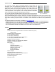
VT7600 series Protocol Implementation Conformance Statement (PICS) Vendor Name: Viconics Vendor ID: 140 Product Name: VT7600 Controller Series Product Model Number: VT7600A5X00B, VT7600B5X00B, VT7605B5X00B, VT7607B5X00B, VT7600H5X00B, VT7652A5X0B, VT7652B5X00B, VT7656B5X00B, VT7657B5X00B, VT7652H5X0B, VT76X6E5X00B, VT76X6F5X00B and VT76X6W5X00B.
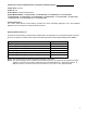
Device Object Table Object Name VT76xxX5x00B Type and Instance Device Object Property Object_Identifier Controller Parameter Unique ID number of a device on a network Property 75 (R,W) Object_Name Unique name of a Device on a network Property 77 (R,W) Model Name Controller Model number Property 70 (R) Firmware Revision Current BACnet firmware revision used by the controller Property 44 (R) Protocol Version Current BACnet firmware protocol version Property 98 (R) Default is Version 1 Protocol
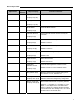
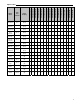
Object Name Type and Instance Object Property VT7600A5x00B VT7652A5x00B VT7600B5x00B VT7652B5x00B VT7605B5x00B VT7656B5x00B VT7607B5x00B VT7657B5x00B VT7600H5x00B VT7652H5x00B VT7600W5x00B VT7652W5x00B VT7606E5x00B VT7656E5x00B VT7600F5x00B VT7652F5x00B Objects Table Room Temperature AV 7 Present_Value (R,W) √ √ √ √ √ √ √ √ √ √ √ √ √ √ √ √ Room Temp Override BV 8 Present_Value (R,W) √ √ √ √ √ √ √ √ √ √ √ √ √ √ √ √ Outdoor Temperature AV 9 Present_V
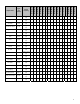
Object Name Type and Instance Object Property VT7600A5x00B VT7652A5x00B VT7600B5x00B VT7652B5x00B VT7605B5x00B VT7656B5x00B VT7607B5x00B VT7657B5x00B VT7600H5x00B VT7652H5x00B VT7600W5x00B VT7652W5x00B VT7606E5x00B VT7656E5x00B VT7600F5x00B VT7652F5x00B PI Heating Demand AV 20 Present_Value (R) √ √ √ √ √ √ √ √ √ √ √ √ √ √ √ √ PI Cooling Demand AV 21 Present_Value (R) √ √ √ √ √ √ √ √ √ √ √ √ √ √ √ √ AI1 Value AI 23 Present_Value (R) √ √ Economizer
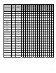
VT7652F5x00B VT7600F5x00B VT7656E5x00B VT7606E5x00B VT7652W5x00B VT7600W5x00B VT7652H5x00B VT7600H5x00B VT7657B5x00B VT7607B5x00B VT7656B5x00B VT7605B5x00B VT7652B5x00B VT7600B5x00B VT7652A5x00B VT7600A5x00B Object Name Type and Instance Object Property Clock Alarm BI 37 Present_Value (R) Filter Alarm BI 38 Present_Value (R) √ √ √ √ √ √ √ √ √ √ √ √ √ √ Service Alarm BI 39 Present_Value (R) √ √ √ √ √ √ √ √ √ √ √ √ √ √ Fan Lock Alarm BI 40 Present_Valu
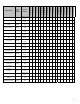
VT7652A5x00B VT7600B5x00B VT7652B5x00B VT7605B5x00B VT7656B5x00B VT7607B5x00B VT7657B5x00B VT7600H5x00B VT7652H5x00B VT7600W5x00B VT7652W5x00B BV 56 Present_Value (R,W) √ √ √ √ √ √ √ √ √ √ √ √ Menu Scroll BV 57 Present_Value (R,W) √ √ √ √ √ √ √ √ √ √ √ √ Supply Heat Lockout Status BV 58 Present_Value (R) General Options 2- GRP 58 Present_Value (R) √ √ √ √ √ √ √ √ √ √ √ Password Value AV 59 Present_Value (R,W) √ √ √ √ √ √ √ √ √ √ Power-up
VT7606E5x00B VT7656E5x00B Present_Value (R,W) √ √ √ √ √ √ √ √ Cooling Stages MV 74 Present_Value (R,W) √ √ √ √ √ √ √ √ Heatpump Stages MV 75 Present_Value (R,W) Economizer Model Configuration Options GRP 76 Present_Value (R) √ √ Fresh Air Max Range AV 76 Present_Value (R,W) √ √ Economizer Changeover Setpoint AV 77 Present_Value (R,W) √ √ √ √ Economizer Minimum Position AV 78 Present_Value (R,W) √ √ √ √ Mechanical Cooling Enabled BV 79 Present_Value (R,W) √
√ √ √ Dehumidification RH Setpoint AV 89 Present_Value (R,W) √ √ √ √ Dehumidification Hysterisys AV 90 Present_Value (R,W) √ √ √ √ Dehumidification Low OA Lockout AV 91 Present_Value (R,W) √ √ √ √ Dehumidification Lockout Functions BV 92 Present_Value (R,W) √ √ Dehumidification Lockout Functions MV 92 Present_Value (R,W) √ √ Dehumidification Output Status BI 93 Present_Value (R) √ √ √ √ Humidification Model Configuration Options GRP 94 Present_Value (R) √ √ AI1
√ √ √ √ √ √ VT7652F5x00B √ VT7600F5x00B Present_Value (R,W) VT7656E5x00B SCH 102 VT7606E5x00B Local Schedule VT7652W5x00B Present_Value (R,W) VT7600W5x00B AV 101 VT7652H5x00B Maximum CO2 Level √ VT7600H5x00B Present_Value (R) VT7657B5x00B AV 101 VT7607B5x00B Humidifier Output VT7656B5x00B Present_Value (R,W) VT7605B5x00B AV 100 VT7652B5x00B Minimum CO2 Level VT7600B5x00B Object Property VT7652A5x00B Type and Instance VT7600A5x00B Object Name √ √ √ √ √ √ 11
Note: Please note that some object type and instant numbers have the same object name. Therefore please make sure to see the table above for more detailed information on each controller model.
List of Property Value Range Restrictions for AI and AV objects Object Type and instance Under range value Over range value Default value Room Temperature AV 7 -40°F (-40°C) 122°F (50°C) N/A Outdoor Temperature AV 9 -40°F (-40°C) 122°F (50°C) N/A Room Humidity AV 11 0% 100% N/A Supply Temp AI 16 -40°F (-40°C) 122°F (50°C) N/A Supply RH AV 17 0% 100% N/A Water Temperature AV 17 -40°F (-40°C) 122°F (50°C) N/A PI Heating Demand AV 20 0% 100% N/A PI Cooling Demand AV 21
Object Type and instance Under range value Over range value Default value Dehumidification Hysterisys AV 90 2% 20% 5% Dehumidification Low OA Lockout AV 91 -40°F (-40°C) 122°F (50°C) 32°F (0°C) Humidification RH Setpoint AV 95 10% 90% 50% Minimum Supply Heat Setpoint AV 95 50°F(10°C) 72°F(20°C) 64°F(18°C) Eff (Effective) Reset Humidification RH Spt (Setpoint) AV 96 0% 100% N/A Supply Heat Lockout Temperature AV 96 -15°F(-26°C) 120°F(49°C) 32°F(0°C) Humidification High Limit
List of Property Enumeration Sets for BI and BV objects Object Name Object Type and instance Inactive_Text Default value Active_Text Room Temp Override BV 8 Normal Override Normal Outdoor Temp Override BV 10 Normal Override Normal Room Humidity Override BV 13 Normal Override Normal AUX BI 24 Off On Off BI 23 G Fan BI 25 Off On Off Y1 Cool BI 26 Off On Off Y2 Cool BI 27 Off On Off W1 Heat BI 28 Off On Off W2 Heat BI 29 Off On Off Reversing Valve BI 30 Off
Object Name Object Type and instance Inactive_Text Active_Text Default value Supply Heat Lock Status BI 58 Off On Inactive Fan Control BV 62 Off On On Fan Purge Delay BV 64 Off On Off Progressive Recovery BV 70 Off Active Off Discharge Air Alarm BI 72 Off On Off Mechanical Cooling Enabled BV 79 Off On Off Comfort Mode BV 84 Comfort Economy Comfort High CO2 Alarm BI 84 Off On Off Reversing Valve Configuration BV 85 Normally Cool Energized in Heating Normally He
List of Property Enumeration Sets for MV Objects Object Name Object Type and instance Occupancy Command MV12 System Mode HPU MV13 System Mode RTU MV14 Fan Mode MV15 Keypad Lockout MV18 Effective Occupancy MV 34 Heating CPH MV53 Cooling CPH MV54 Temporary Occupancy Time MV61 BACnet Index Text 1 2 3 1 2 3 4 5 1 2 3 4 1 2 3 1 2 3 1 2 3 Local Occupancy Occupied Unoccupied Off Auto Cool Heat Emergency Off Auto Cool Heat On Auto Smart Level 0 Level 1 Level 2 Occupied Unoccupied Temporary O
Object Name Object Type and instance Anticycle MV63 DI1 Configuration MV65 DI2 Configuration MV66 Proportional Band MV 67 Event Display MV71 Heating Stages MV73 Cooling Stages MV74 Heat Pump Stages MV75 Dehumidification Lockout Functions MV 92 BACnet Index Text 1 2 3 4 5 6 1 2 3 4 5 6 1 2 3 4 5 6 1 2 3 4 5 6 7 0 minute 1 minute 2 minutes 3 minutes 4 minutes 5 minutes None RemNSB RemOVR Filter Service Fan lock None RemNSB RemOVR Filter Service Fan lock 2 2F 3 3F 4 4F 5 5F 6 6F 7 7F 8 8
Integration – Global Commands The following figure shows which objects from the controller can be monitored and commanded from the BAS frontend.
Integration – Typical Graphic User Interface (GUI) Objects The following objects should be typically used in a GUI: ¾ ¾ ¾ ¾ ¾ ¾ ¾ ¾ ¾ ¾ ¾ ¾ ¾ ¾ ¾ ¾ ¾ ¾ ¾ ¾ ¾ Room Temperature (AV7); Occupied and Unoccupied Heat Setpoints (AV 42 and AV44); Occupied and Unoccupied Cool Setpoints (AV 43 and AV45); Outdoor Temperature (AV9); Supply Temperature (AI16) (If available); Occupancy Command (MV12); Effective Occupancy (MV34); System Mode RTU (MV14) or System Mode HPU (MV13); G Fan (BI25); Y1 Cool (BI26); Y2 Cool (BI2
Configuration Objects The following objects and group objects should be typically used for configuration purposes: ¾ ¾ ¾ ¾ ¾ ¾ ¾ ¾ General Options 1 Group GRP 46 and its complete list of objects; General Options 2 Group GRP 58 and its complete list of objects; With schedule Model Configuration Options Group GRP 69 and its complete list of objects; Stages Configuration Options Group GRP 72 and its complete list of objects; Economizer Model Configuration Option Group GRP 76 and its complete list of objects;
Cable Type Viconics recommends the use of balanced 22-24 AWG twisted pair with characteristic impedance of 100-130 ohms, capacitance of 30 pF/ft or lower. A braided shield is also recommended. Impedance A value based on the inherent conductance, resistance, capacitance and inductance that represent the impedance of an infinitely long cable. The nominal impedance of the cable should be between 100Ωand 120Ω. However using120Ω will result in a lighter load on the network.
Maximum Number of Devices A maximum of 64 nodes is allowed on a single daisy chain segment. A node is defined as any device (Panel, Zone, Repeater, etc) connected to the RS485 network. Terminators do not count as a node. To determine the number of nodes on a network, add the following: ¾ ¾ One node for each device, including main panels One node for each repeater on the chain For the example in Figure 4, we have one node for the main Panel, plus 4 for the controllers, for a total of 5 nodes.
Figure 5: Correct usage – repeaters are daisy chained to the supervisory controller and separate daisy chains branch from each repeater. Do not install repeaters in series, as this may result in network reliability problems. Figure 6 demonstrates an incorrect use of a repeater in an EIA-485 network.
End Of Line (EOL) Resistors MS/TP network must be properly terminated. For daisy chain configurations, you must install an EOL resistor at each end of the daisy chain. Depending on your MSTP network configuration, the resistance value of the EOL resistor may change: • Viconics’ devices are installed at both ends of the MSTP network: 120 Ohms resistor should be installed at each end.
Table 2 shows the different possibilities with the Status LED behaviour of the BACnet module.
Integrating Viconics’ Devices on an MSTP Network Before doing any BACnet integration, make sure to have Viconics’ PICS (Protocol Implementation Conformance Statement). This PICS document lists all the BACnet Services and Object types supported by a device and can be found at www.viconics.com. Viconics’ devices do not support the COV service. COV reporting allows an object to send out notices when its Present-Value property is incremented by a pre-defined value.
Tips and Things You Need To Know ¾ Each controller is delivered from the factory with the default MAC address set at 254. At this value, the BACnet communication is NOT active and the device will not participate in the token pass either. The local LED status for the communication adapter at this point is one short flash only. To enable the BACnet communication, set the local MAC address configuration property of the controller to any valid value from 0 to 127.
Troubleshooting Section Error / Trouble Condition Controller does not come online Possible Cause Solution Two or more controllers have the same MAC address. The MS/TP network has too many devices. Too many devices were installed without any repeaters. The MS/TP cable runs are broken Modify each duplicate address to a unique number. Do not exceed the maximum number of devices and maximum length allowed by the EIA-485 specifications. Repeaters need to be installed as specified in this document.