PIR Ready VT7600W Series With & Without Local Schedule Water Source Heat Pump Terminal Equipment Controllers Installation Guide F o r C o m m e r c i a l H V AC Ap p l i c a t i o n s May 3rd, 2012 / 028-0355-R4 CONTENTS Installation Location Installation Theory of operation Features overview Model Chart Network ready Terminal, Identification and Function Wiring Screw terminal arrangement Main outputs wiring Typical applications Remote sensor accessories Configuring and Status Display Instructions Status
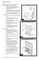
I NSTALLATION Remove the security screw on the bottom of Terminal Equipment Controller cover. Open unit by pulling on the bottom side of Terminal Equipment Controller (fig. 1). Remove wiring terminals from sticker. Please read the FCC ID and IC label installed in the cover upon removal of cover for the wireless products. Location 1. Should not be installed on an outside wall. 2. Must be installed away from any direct heat source. 3. Should not be installed near an air discharge grill. 4.
10. Insert each wire according to wiring diagram. 11. Gently push excess wiring back into hole (fig. 3). 12. Re-Install wiring terminals in their correct locations (fig. 3). 13. Re-install the cover (top side first) and gently push extra wire length back into the hole in the wall. 14. Install security screw. When replacing an existing Terminal Equipment Controller, label the wires before removal of the Terminal Equipment Controller. Electronic controls are static sensitive devices.
Remote discharge air temperature sensor input for monitoring purpose Remote water temperature sensor input for monitoring purpose Lockable keypads for tamper proofing. No need for a separate guards Anti short cycle and minimum on/off run time protection. Reduces wear and maximizes life span of mechanical equipment. 2 configurable digital inputs for added flexibility.
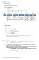
MODEL CHART Network ready All Viconics VT7600 series Terminal Equipment Controllers are designed for stand-alone (Network Ready) operation. They can be fully integrated into your choice of automation systems using the available communication adapter options.
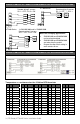
TERMINAL , IDENTIFICATION AND FUNCTION Wiring Water Source Heat Pump Part Number VT7652W VT7600W Schedule Yes No Y2 Y1 G RC C Top left terminal block X X X X X X X X X X Top right terminal block DEH O/B X X X X Bottom terminal block Aux DI1 DI2 RS Scom WS MS X X X X X X X 6 | PIR Ready VT76xxW Series-Installation Guide X X X X X X X
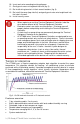
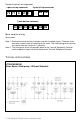
Screw terminal arrangement 5 pole left top connector Y2 Y1 2 pole left top connector G RC C DEH O/B 7 pole bottom connector AU D1 D2 RS Scom WS MS Main outputs wiring Wiring notes: Note 1: Electromechanical contacts are to be used with the digital inputs. Electronic triacs cannot be used as mean of switching for the input.
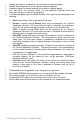
Remote sensor accessories MODEL NO. S3010W1000 S3020W1000 DESCRIPTION Wall mounted temperature sensor Wall mounted temperature sensor+override button and occupancy status S2060A1000 Averaging temperature sensor S2000D1000 Duct mounted temperature sensor Remote mount temperature sensors use 10K NTC thermistor.
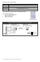
WIRING EXAMPLES OF 2 REMOTE ROOM SENSORS FOR AVERAGING APPLICATIONS: VT7600 Series 2x S3020W1000 Remote wiring 2 sensors S2-1 = OFF / S2-2 = ON 2x S3010W1000 Remote wiring 2 sensors S2-1 = OFF / S2-2 = S c o m S c o m ON VT7600 Series S c o m S c o m S co m S co m R S R S R S A u x C C C D I D I A u x A U C R S A U R S R S 1 D 2D 1 D 2D VT7600 Series 1x S3010W1000 and 1x S3020W1000 Remote wiring 2 sensors S2-1 = OFF / S2-2 = ON Notes for averaging applications: S c o m S co m S c
-28 -18 151.6239 -8 18 48.7042 12 54 17.9636 32 90 7.4182 52 126 3.3568 -27 -17 142.7211 -7 19 46.1933 13 55 17.1440 33 91 7.1150 53 127 3.2333 -26 -15 134.3971 -6 21 43.8268 14 57 16.3665 34 93 6.8259 54 129 3.1150 -25 -13 126.6109 -5 23 41.5956 15 59 15.6286 35 95 6.5499 55 131 3.0016 -24 -11 119.3244 -4 25 39.4921 16 61 14.9280 36 97 6.2866 56 133 2.8928 -23 -9 112.5028 -3 27 37.5056 17 63 14.2629 37 99 6.0351 57 135 2.7886 -22 -8 106.
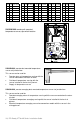
WIRING S2000D1000, S2060A1000 AND S2020E1000 Remote wiring 1 sensor Remote wiring 4 sensors RS or Scom MS or Scom Scom OS RS or Scom MS or Scom 10 K 10 K ( Scom 10 K 10 K 10 K OS User menu flow chart: NOTE: Prompts may not all be present depending on model selected MENU If status is: Unoccupied Override schd Y/N If status is: Temporary Occupied Time, Temperat set? Y/N Sys mode set? Y/N off heat cool auto Fan mode set? Y/N Cancel ovrd Y/N Appears on stand-alone models only C
Status display The Terminal Equipment Controller features a two-line, eight-character display. There is a low level backlight level that is always active and can only be seen at night. When left unattended, the Terminal Equipment Controller has an auto scrolling display that shows the actual status of the system. Each item is scrolled one by one with the back lighting in low level mode. Pressing any key will cause the back light to come on to high level.
Frost ON SetClock Service Filter Fan lock Indicates that the heating is energized by the low limit frost protection room temperature setpoint 5.6 °C ( 42 °F ) Indicates that the clock needs to be reset.
If the user pauses at any given time during configuring, Auto Help text is displayed to help and guide the user through the usage and configuring of the Terminal Equipment Controller. Ex.: Press yes key to change cooling temperature setpoint Use the up or down arrow to adjust cooling setpoint Local keypad interface Each of the sections in the menu is accessed and configured using 5 keys on the Terminal Equipment Controller cover.
Sequence of user menu: SYSTEM FAN OVERRIDE TEMPERATURE SCHEDULES CLOCK SCHEDULE MODE MODE RESUME SETPOINTS SETTING SETTING HOLD SETTING SETTING Override schd Y/N Temperat Set Y/N Sys mode set Y/N Fan mode set Y/N Appears only in unoccupied mode Schedule set Y/N Clock set Y/N Schedule hold Y/N Appears only on stand-alone (Network Ready) models Cancel ovrd Y/N Appears only in override mode Occupied setpoints adjustments There is a default profile set in the Terminal Equipment Controller from the fact
A) Override an unoccupied period Override schd Y/N This menu will appear only when the Terminal Equipment Controller is in unoccupied mode. The unoccupied mode is enabled either by the internal timer scheduling or by a remote NSB contact via DI1 or DI2. If DI1 or DI2 is configured to operate as a remote temporary override contact, this menu will be disabled.
Local changes to the heating or cooling setpoints made by the user directly using the up or down arrow are temporary. They will remain effective for the duration specified by ToccTime. Setpoints will revert back to their default value after internal timer ToccTime expires.
F) Schedule set (2 events) Scheduling can have 2 or 4 events per day. This is set in the configuration menu as per parameter (2/4event) Schedule set Y/N This section of the menu permits the user to set the whether 2 or 4 events is needed. Each day can be tailored to specific schedules if needed. 2 events can be scheduled per day. Occupied & unoccupied periods can be set for each day.
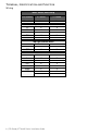
Ex. #2 Commercial building which is occupied all weekend Event Setpoint Monday Tuesday Wednesday Thursday Friday Saturday Sunday Period #1 - Event #1 Occupied Cool Heat 72 °F 70 °F 8.00 AM 8.00 AM 8.00 AM 8.00 AM 8.00 AM 12.00 AM ** 12.00 AM ** Period #1 - Event #2 Unoccupied Cool Heat 80 °F 62 °F 5.00 PM 5.00 PM 5.00 PM 5.00 PM 5.00 PM 11.59 PM ** 11.
Ex. #1 Four event retail establishment schedule Monday Tuesday Wednesday Period 1 Event 1 Occupied Cool Heat 72°F 70°F 7.00 AM 7.00 AM 7.00 AM Period 1 Event 2 Unoccupied Cool Heat 80°F 62°F 5.00 PM 5.00 PM 5.00 PM Period 2 Event 3 Occupied Cool Heat 72°F 70 °F 12.00 PM * 12.00 PM * 12.00 PM * Period 2 Event 4 Unoccupied Cool Heat 80°F 62 °F 12.00 PM * 12.00 PM * 12.00 PM * Thursday 7.00 AM 5.00 PM 7.00 PM 10.30 PM Event Setpoint Friday 7.00 AM 5.00 PM 7.00 PM 10.30 PM Saturday Sunday 12.
H) Clock/Day Settings Clock set Y/N This section of the menu permits the user to set the time and day. Time setting Time set? Y/N Time 0:00 No next Yes down Use ▲▼ To set value Day setting Day set? Y/N Day Monday No next Yes down Use ▲▼ To set value Time format setting 12/24hrs set? Y/N 12/24hrs 12 hrs No = exit Yes down Use ▲▼ To set value J) Schedule hold Schedule hold Y/N This menu will only appear on stand-alone (Network Ready) Terminal Equipment Controller, i.e.
Schedule uno hold Hold permanent unoccupied forces the Terminal Equipment Controller into a permanent unoccupied mode using the unoccupied setpoints. All timed scheduling functions are by-passed. The PERMANENT UNOCCUPIED status will appear in the automatic status scroll. To resume to regular scheduling, user must scroll to the Schedule Hold menu and select the Schedule resume option.
CONFIGURATION PARAMETERS DEFAULT VALUE SIGNIFICANCE AND ADJUSTMENTS PswrdSet Configuration parameters menu access password Default value = 0 No password prompted This parameter sets a password access to prevent unauthorized access to the configuration menu parameters. A default value of “0” will not prompt a password or lock the access to the configuration menu.
Channel Channel selection Default value = 10 Range is: 10 to 26 Conditional parameter to Wireless models (VT76xxW5x00W) This parameter will only appear when a wireless network adapter is present.
DI 1 (None) : No function will be associated with the input Digital input no.1 configuration (Rem NSB): remote NSB timer clock input. Will disable the internal scheduling of the Terminal Equipment Controller. The scheduling will now be set as per the digital input. The time is still displayed as information, but the menu part related to scheduling is disabled and no longer accessible.
lockout Keypad lockout levels 0 = No lock 1 = Low level Default value = 0 No lock 2 = High level 0 1 2 pwr del Power-up delay Default value = 10 seconds Frost pr Frost protection enabled Default value = Off Permanent hold Clock setting Schedules setting Fan mode setting System mode setting Temporary setpoints using arrows Permanent Occupied and Unoccupied Setpoints Resume/ Override scheduling LEVEL USER KEY FUNCTIONS On initial power up of the Terminal Equipment Controller (each time 24 Vac pow
Pband Proportional Band setting Default value 2 = 2.0 °F ( 0.6 °C ) Adjust the proportional band used by the Terminal Equipment Controller PI control loop. Note that the default value of 2.0 °F ( 1.1 °C ) gives satisfactory operation in most normal installation cases. The use of a superior proportional band different than the factory one is normally warranted in applications where the Terminal Equipment Controller location is problematic and leads to unwanted cycling of the unit.
deadband Minimum deadband Default value = 2.0 °F ( 1.1 °C ) fan cont Fan control Default value = On Minimum deadband value between the heating and cooling setpoints. If modified, it will be applied only when any of the setpoints are modified. 2, 3 or 4 °F ( 1.0 to 2.0 °C ) Fan control in heating mode. When selecting On; the Terminal Equipment Controller in all cases will always control the fan (terminal G).
HP stage Number of heatpump stages Default value = 2 stages Will revert the operation of 2 stage Terminal Equipment Controller to single stage operation only when the second compressor step is not needed. 1 or 2 stages H lock Outside air temperature heating lockout Default value = 120 °F ( 49 °C ) Disables heating stage operation based on outdoor air temperature. Function will only be enabled if OS ( outside air temperature network value ) is received.
aux cont Auxiliary contact configuration Default value = N.O. normally open This contact can be used to energize peripheral devices such as: lighting equipment, exhaust fans, economizers, etc. This contact will operate in parallel with the internal occupied/unoccupied schedule of the Terminal Equipment Controller or the remote NSB contact if DI1 or DI2 is used. When the system is in OFF mode, the contact will remain in its unoccupied status independently of the occupied / unoccupied schedule. Configured N.
Dhu set Dehumidification setpoint Default is 50 % RH DHumiLCK Dehumidification lockout Default value: Restrict Used only if dehumidification sequence is enabled: Range is: 30-95% RH Enables, restricts or disables the dehumidification sequence.
TROUBLESHOOTING GUIDE All models Symptom No display on the Terminal Equipment Controller Possible Cause Absent or incorrect supply voltage Overloaded power transformer Keyboard menu does not access all functions Keyboard locked Temperature setpoints revert to original value after a certain time period Temporary setpoint option selected Terminal Equipment Controller will not call for heating Wrong mode selected Terminal Equipment Controller in Unoccupied mode Anticycle delay active Corrective Action
Wiring error Wrong mode selected The Terminal Equipment Controller will not turn on the fan Digital display shows missing digits or erratic segments Wiring error 1. Start the Fan by forcing the Fan ON mode 2. Put a jumper across terminals RC & Y1. The cooling should come ON. If it does not, verify wiring 1. Start the Fan by forcing the Fan ON mode 2. Put a jumper across terminals RC & G. The fan should come ON.
S PECIFICATIONS Terminal Equipment Controller power requirements: Operating conditions: Storage conditions: Temperature sensor: Temperate sensor resolution: Temperature control accuracy: Contact output rating Occ, Stand-By and Unocc cooling setpoint range: Occ, Stand-By and Unocc heating setpoint range: Room and outdoor air temperature display range: Proportional band for room temperature control: Digital inputs: Wire gauge: Approximate shipping weight: Agency Approvals all models: Agency Approvals all mod
DRAWING & DIMENSIONS Viconics Technologies Inc. Tel.: Fax: Toll free: www.viconics.