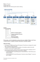
VT7600E Series RTU Terminal Equipment Controller with IAQ Control Installation Guide For Commercial HVAC Applications February 25th, 2014 / 028-0363-02 Contents Installation 2 Location 2 Installation 2 Theory of Operation 4 Features overview 4 Model Chart Network ready Terminal, Identification and Function Screw terminal arrangement and wiring 5 5 6 6 Typical applications 7 Main outputs wiring 7 Remote sensor accessories 8 Configuring and Status Display Instructions 9 Status display
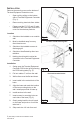
Installation Remove the security screw on the bottom of Terminal Equipment Controller cover. • Open unit by pulling on the bottom side of Terminal Equipment Controller (Fig. 1). • Remove wiring terminals from sticker. • Please read the FCC ID and IC label installed in the cover upon removal of cover for the wireless products. Location 1. Should not be installed on an outside wall. 2. Must be installed away from any direct heat source. 3. Should not be installed near an air discharge grill. 4.
10. Insert each wire according to wiring diagram. 11. Gently push excess wiring back into hole (Fig. 3). 12. Re-Install wiring terminals in their correct locations (Fig. 3). 13. Re-install the cover (top side first) and gently push extra wire length back into the hole in the wall. 14. Install security screw. • If replacing an existing Terminal Equipment Controller, label the wires before removal of the Terminal Equipment Controller. • Electronic controls are static sensitive devices.
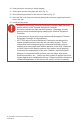
Theory of Operation The VT76X6E series uses a Viconics proprietary adaptive logic algorithm to control the space temperature. This algorithm controls the heating or air conditioning system to minimize overshoot while still providing comfort. It provides exceptional accuracy due to its unique PI time proportioning control algorithm, which virtually eliminates temperature offset associated with traditional, differential-based On-Off thermostats. Fig.2 - On-Off mechanical control vs PI electronic control.
Model Chart Product Selector Please refer to the following matrix when ordering Example: VT765 6 E 5500W Wireless communication Factory installed PIR cover IAQ Control With Economizer Local Scheduling Please note, not all combinations and variants are available. Refer to the Viconics price list for a complete selection listing of all available models. Network ready • • • All Viconics VT7600 series Terminal Equipment Controllers are designed for standalone (Network Ready) operation.
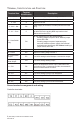
Terminal, Identification and Function Terminal Use Terminal Identification 1 – Cool 2 Y2 Output for cooling / compressor stage number 2. 2 – Cool 1 Y1 Output for cooling / compressor stage number 1. 3 - Fan G Output for the fan. 4 - 24 V ~ Hot RC 5 - 0 V ~ Com C Description Power supply of controller, hot side (Delivered from the RTU). Power supply of controller, common side. Also used as reference for the analog BPD output when used (Delivered from the RTU).
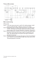
Typical Applications Main outputs wiring Wiring notes: Note 1: If the same power source is used for the heating stages, install jumper across RC & RH. Maximum current is 2.0 amps. Note 2: Economizer and all analog outputs and inputs use a half bridge rectifier. Reference of the control signal is the common of the power supply of the Terminal Equipment Controller. (Terminal C). Note 3: Electromechanical contacts are to be used with the digital inputs.
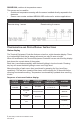
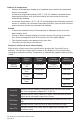
Remote sensor accessories Model no. Description S2020E1000 Outdoor temperature sensor S2060A1000 Averaging temperature sensor S2000D1000 Duct mounted temperature sensor Remote mount temperature sensors use 10K type 2 NTC thermistors. Temperature vs. resistance chart for 10 Kohm NTC thermistor (R25°C = 10KΩ±3% - B25/85°C = 3975K±1.
S2020E1000; outdoor air temperature sensor This sensor can be used for: • Outside air temperature sensing with the sensor installed directly exposed to the elements. • Sensor uses a water resistant NEMA 4 ABS enclosure for outdoor applications. WIRING S2000D1000, S2060A1000 and S2020E1000 Remote wiring 1 sensor Remote wiring 4 sensors Configuration and Status Display Instructions Status display The Terminal Equipment Controller features a two-line, eight-character display.
Outdoor air temperature • Outdoor air temperature display is only enabled when outdoor air temperature sensor is connected. • A maximum range status display of 50 °C (122 °F) indicates a shorted sensor. Associated functions, such as mode lockouts and economizer function are automatically disabled. • A minimum range status -40 °C (-40 °F) is not displayed and indicates a opened sensor or a sensor not connected. Associated functions, such as mode lockouts and economizer function are automatically disabled.
User Interface When any of the fan is ON, the FAN LED will illuminate When heating & reheat is ON, the HEAT LED will illuminate When cooling is ON, the COOL LED will illuminate User configuring instructions menu The VT76X6E series of controllers feature an intuitive, menu-driven, back-lit LCD display that walks users and installers through the configuring steps, making the configuring process extremely simple.
When left unattended for 45 seconds, the display will resume automatic status display scrolling. To turn on the back light, press any key on the front panel.
Cooling setpoint Occupied mode Heating setpoint Occupied mode Cooling set? Y/N No next → Yes down ↓ Heating set? Y/N Cooling 70.0 °F Use ▲▼ To set value Heating 68.00 °F Cooling setpoint Unoccupied mode Heating setpoint Unoccupied mode No next → No next → No next → Unocc CL Unocc HT Yes down Yes down Yes down set? Y/N set? Y/N ↓ ↓ ↓ Use ▲▼ keys to set value, Yes key to confirm Use ▲▼ To set value Unocc CL 80.0 °F Use ▲▼ To set value Unocc HT 60.
E) Fan mode setting Fan mode set Y/N This section of the menu is permits the setting of the fan mode operation. Use ▲▼ to set value, Yes key to confirm. Fan mode On On fan mode Fan is on continuously, even when system mode is OFF. Fan mode Auto Automatic fan mode Fan cycles on a call for heating or cooling for both occupied & unoccupied periods. Fan mode Smart Smart fan mode During occupied periods, fan is on continuously. In unoccupied mode, fan cycles on a call for heating or cooling.
Typical examples of a 2 event office schedule Ex. #1 Office building closed all weekend Event Setpoint Monday Tuesday Wednesday Thursday Friday Saturday Sunday Period #1 - Event #1 Occupied Cool Heat 70 °F 72 °F 7.00 AM 7.00 AM 7.00 AM 7.00 AM 7.00 AM 12.00 PM * 12.00 PM * Period #1 - Event #2 Unoccupied Cool Heat 80 °F 62 °F 6.00 PM 6.00 PM 6.00 PM 6.00 PM 6.00 PM 12.00 PM * 12.
G) Schedule set (4 events) Schedule set Y/N This section of the menu permits the user to set the whether 2 or 4 events is needed. Each day can be tailored to specific schedules if needed. • 4 events can be scheduled per day. • Occupied and Unoccupied periods can be set for each day. • Scheduling the 3rd. & 4th. Events to the same time will cancel the last period.
Ex. #1 Four event retail establishment schedule Event Period #1 Event #1 Occupied Cool Heat Setpoint 72 °F 70 °F Monday 7.00 AM Tuesday 7.00 AM Wednesday 7.00 AM Thursday 7.00 AM Friday 7.00 AM Saturday 12.00 PM * Sunday 12.00 PM * Period #1 Event #2 Unoccupied Cool Heat 80 °F 62 °F 5.00 PM 5.00 PM 5.00 PM 5.00 PM 5.00 PM 12.00 PM * 12.00 PM * Period #2 Event #3 Occupied Cool Heat 72 °F 70 °F 12.00 PM * 12.00 PM * 12.00 PM * 7.00 PM 7.00 PM 12.00 PM * 12.
H) Clock/Day Settings Clock set Y/N This section of the menu permits the user to set the time and day. Time setting Day setting Time format setting Time set? Y/N No next → Yes down ↓ Day set? Y/N No next → Yes down ↓ 12/24hrs set? Y/N No = exit Yes down ↓ Time 0:00 Use ▲▼ To set value Day Monday Use ▲▼ To set value 12/24hrs 12 hrs Use ▲▼ To set value I) Schedule hold Schedule hold Y/N • This menu will only appear on stand-alone (Network Ready) Terminal Equipment Controller, i.e.
CONFIGURATION PARAMETERS DEFAULT VALUE PswrdSet Configuration parameters menu access password Default value = 0 Range is: 0 to 1000 Com addr Thermostat networking address Default value = 254 Range is: 0 to 254 PAN ID Personal Area Network Identification Default value = 0 Range is: 0 to 500 SIGNIFICANCE AND ADJUSTMENTS This parameter sets a password access to prevent unauthorized access to the configuration menu parameters.
Channel Channel selection Default value = 10 Range is: 10 to 26 Conditional parameter to Wireless models VT76xxX5x00W This parameter will only appear when a wireless network adapter is present. If the Terminal Equipment Controller is installed as a stand-alone (Network Ready) unit or with a BACnet® or Echelon® adapter, this parameter will not be used or displayed.
Permanent hold Clock setting Schedules setting Fan mode setting System mode setting Temporary setpoints using arrows Permanent Occupied and Unoccupied Setpoints Resume/ Override scheduling LEVEL USER KEY FUNCTIONS 0 1 2 pwr del Power-up delay Default value = 10 seconds On initial power up of the Terminal Equipment Controller (each time 24 VAC power supply is removed & re-applied) there is a delay before any operation is authorized (fan, cooling or heating).
Pband Proportional band setting Default value 2 = 2.0 °F (1.1 °C) Anticycle Minimum On-Off operation time for stages Default value = 2 minutes Adjust the proportional band used by the Terminal Equipment Controller PI control loop. Note that the default value of 2.0 °F (1.1 °C) gives satisfactory operation in most normal installation cases.
Cool cph Cooling stages cycles per hour Default value = 4 C.P.H. Will set the maximum number of cooling stage cycles per hour under normal control operation. It represents the maximum number of cycles that the equipment will turned on and off in one hour. Note that a higher C.P.H will represent a higher accuracy of control at the expense of wearing mechanical components faster. 3 or 4 C.P.H.
Cal OS Outside air temperature sensor calibration Default value = 0.0 °F or °C Offset that can be added/subtracted to the actual displayed outdoor temperature. H stage Number of heating stages. Applicable to 2 stage models only Default value = 2 stages Will revert the operation of 2 stages Terminal Equipment Controller to single stage operation only when the second heating step is not needed.
2/4event Number of events configuration Default value = 2 event Prog rec Progressive recovery enabled Default value = Off Progressive recovery is automatically disabled if DI 1 and / or DI 2 are configured remote NSB 2 events, will set up scheduling for the following Event 1 is for Occupied setpoints Event 2 is for Unoccupied setpoints 4 events, will set up scheduling for the following Event 1 is for Occupied setpoints Event 2 is for Unoccupied setpoints Event 3 is for Occupied setpoints Event 4 is for Un
C mech In Cooling mode. Mechanical cooling allowed Allows the operation of the mechanical cooling if the free cooling ( economizer ) cannot maintain the cooling setpoint. Default value = Off Off Typically applies when the MS ( mixed air temperature sensor ) is installed after the mechanical cooling refrigeration coils. In this case, mechanical cooling will never operate at the same time as free cooling.
Minimum Fresh Air Damper/Economizer Position Minimum fresh air damper position. Effective only in Occupied mode (Fan is ON). This value is also used to determine the fresh air damper position based on the Min/Max CO2 and Min/Max Pos values set. See Fresh Air Damper Position section for more details. Default value = 0% 0% to 100%, 1 or 10 increments Max Pos Maximum fresh air damper position. Effective only in Occupied mode (Fan is ON).
Max CO2 Maximum CO2 Level Default value = 1200 ppm Maximum CO2 Level allowed. Effective only in Occupied mode (Fan is ON). This value is used to determine the fresh air damper position based on the Min/Max CO2 and Min/Max Pos values set. See Fresh Air Damper Position section for more details. 0 to 2000 ppm, 10 or 100 increments MS dis Display mixed air temperature, only if sensor is installed. Used as diagnostic / service help to troubleshoot and diagnose economizer operation.
Fresh Air Damper Control Sequences The fresh air damper can be controlled through more than one sequence to achieve different control strategies such as free cooling (economizer mode), minimum fresh air control and CO2 level control. Here are the control sequences available: Note: For the sequences mentioned below, the following conditions must be met in order for the sequences to be performed as stated: -- Max Pos parameter value must be greater than Min Pos Parameter value.
Economizer Mode and Fresh Air Measurement Station If the fresh air damper is to be used for both free cooling and minimum fresh air volume control (economizer mode and fresh air measurement station, but without CO2 level control), only the Min FA parameter and the free cooling sequence will be active. -- The FA Range parameter should be set to a value higher than 0 CFM (0 CFM disables the fresh air control). -- Min FA (minimum fresh air) parameter should be set to the desired level.
Economizer Mode and CO2 Level Control If the fresh air damper is to be used for both free cooling and CO2level control (economizer mode and CO2 level control, but without fresh air measurement station), only the Min Pos, Max Pos, Min CO2and Max CO2 parameters as well as the free cooling sequence will be active. -- The FA Range parameter should be set to 0 CFM.
Economizer Mode, CO2 Level Control and Fresh Air Measurement Station If the fresh air damper is to be used for both free cooling and CO2 level control with a fresh air measurement station, only the Min FA, Max FA, Min CO2 and Max CO2 parameters as well as the free cooling sequence will be active. -- The FA Range parameter should be set to something other than 0 CFM.
Specifications Terminal Equipment Controller power requirements: 19-30 VAC 50 or 60 Hz; 2 VA Class 2 Operating conditions: 0 °C to 50 °C (32 °F to 122 °F) 0% to 95% R.H. non-condensing Storage conditions: -30 °C to 50 °C (-22 °F to 122 °F) 0% to 95% R.H. non-condensing Sensor: Local 10 K NTC thermistor Resolution: ± 0.1 °C (± 0.2 °F) Temperature control accuracy: ± 0.5 ° C (± 0.9 °F) @ 21 °C (70 °F) typical calibrated Contact output rating: Relay output: 30 VAC, 1 Amp. Maximum, 3 Amp. In-rush.
Drawing & Dimensions Viconics Technologies Inc. 9245 Langelier Blvd. I St-Leonard I Quebec I Canada I H1P 3K9 Tel.: (514) 321.5660 I Fax: (514) 321.4150 Toll free: 1 800.563.5660 sales@viconics.com I www.viconics.