PIR Ready7 VT76x7 Series Programmable & Non-Programmable Thermostats For Commercial HVAC Applications LonWorks Integration Manual ITG-VT760x7-PIR-LON-E01 (028-6007 R1 - Issue Date: May 30, 2008) 1
Product Overview The VT76x7 PI thermostat family is specifically designed for single stage and multi-stage control of heating/cooling equipment such as rooftop and self-contained units with humidifier and/or dehumidifier. The product features an embedded complete humidity solution with an intuitive, menudriven, backlit LCD display that walks users through the programming steps, making the process extremely simple.
PID History Revision Table XIF, APB and NXE File Names and Corresponding PIDs. This manual information is to be used only with the current released VT76x7 PIR ready thermostats. Used on current APB / NXE / XIF file Revision Level Associated PID released thermostat names PIR Ready VT76x7 Series VT76RH_PIR.XIF Rev 4.0 80:00:C5:55:00:04:04:22 This manual information is NOT to be used only with the previously released VT76x7 thermostats.
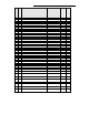
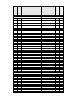
0 1 2 3 4 5 6 7 8 9 10 11 12 13 nviSpaceTemp nviOutdoorTemp nviOccManCmd nviApplicMode nviSetpoint nviTimeSet nciDaySched[0] nciDaySched[1] nciDaySched[2] nciDaySched[3] nciDaySched[4] nciDaySched[5] nciDaySched[6] nciSetPts 1 occupied_cool 3 unoccupied_cool 4 occupied_heat 6 unoccupied_heat 14 nciCfg1RtuHp Associate with UNVT_cfg_1_rtu_hp format file 1 password 2 unoccupied_timer 3 anticycle 4 power_up_delay 5 temporary_occ_time 6 heating_stages_CPH 7 cooling_stages_CPH 8 heat_maximum_setpoint 9 cool_mini
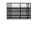
VT7657B5x00E VT7607B5x00E UNVT_cfg_3_rtu_rh X X Enumeration Set Used: input_cfg_model_d_t Enumeration Set Used: aux_contact_cfg_t Enumeration Set Used: nb_of_events_t Enumeration Set Used: off_on_state_t Unsigned-Short Unsigned-Short Enumeration Set Used: off_on_state_t SNVT_temp_p SNVT_temp_p SNVT_temp_p SNVT_lev_percent SNVT_lev_percent SNVT_lev_percent Signed-Long SNVT_lev_percent SNVT_lev_percent Enumeration Set Used: off_on_state_t SNVT_hvac_type UNVT_model_info_2 x x x x x N/A x N/A x x
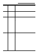
VT7657B5x00E VT7607B5x00E UNVT_rh_status X X local_humidity_level SNVT_lev_percent x x supply_humidity_level SNVT_lev_percent x x effective_reset_humid_setpoint SNVT_lev_percent x x pi_humid_demand_output SNVT_lev_percent x x dehumid_output_active x x X X X X 23 Sub No Snivet Type Point Name nvoRHStatus Enumeration and Signature Type Associate with UNVT_rh_status format file 24 nvoEffectSetpt Enumeration Set Used: off_on_state_t SNVT_temp_p 25 nvoSetpoint SNVT_temp_p
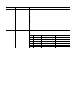
Input Network Variables (nvi’s) Description Parameter Room Temperature Variable Name network input SNVT_temp_p nviSpaceTemp Outdoor Air Temperature network input SNVT_temp_p nviOutdoorTemp Occupancy network input SNVT_occupancy nviOccManCmd Function This input network variable provides a network remote temperature value to the thermostat. If a valid value is present, the internal temperature reading (internal sensor) is no longer used.
Parameter Occupied Cool & Heat Setpoints Variable Name network Input SNVT_temp_p nviSetpoint Date and time network input SNVT_time_stamp nviTimeSet Function This input network variable is used to allow the occupied temperature setpoints only to be changed via the network from a single analog value. (Note: the Unoccupied setpoints are not changed). The corresponding heating and cooling values are derived from the minimum deadband configuration value Default Null Value: 621.81°F (327.67°C or 0x7FFF) Ex.
Output Network Variables (nvo’s) Description All output network variables will be updated no faster than the Minimum Send Time (nciMinOutTm) configuration value, if used. An output network variable will be transmitted immediately when its value has changed significantly. Additionally, this variable will also be transmitted as a heartbeat output on a regular basis as dictated by the Maximum Send Time (nciSndHrtBt) configuration value.
Parameter Occupancy Variable Name network output SNVT_occupancy nvoEffectOccup Thermostat’s I/O status network output UNVT_thermo_state _rh nvoSccStatus Function This output network variable is used to indicate the actual occupancy mode of the unit.
Parameter Thermostat’s I/O status Setpoint Variable Name network output UNVT_rh_status nvoRHStatus network output SNVT_temp_p nvoEffectSetpt Function This network variable output is used to report the Space Comfort humidity function’s status Name Valid value local humidity level 0 to 100% RH supply humidity level 0 to 100% RH effective reset humid setpoint 0 to 100% RH pi humid demand output 0 to 100% demand dehumid output active 0 = Dehumidification not active 1 = Dehumidification active This output ne
Configuration properties (nci’s) Description Parameter Schedule Temperature Setpoints Thermostat’s common configuration parameters network input config Variable Name Function network input config This configuration property defines the schedule for every day of UNVT_day_sched the week (from Monday to Sunday or from day 0 to day 6). This nci is linked with the nvoEffectOccup variable. nciDay_Sched[x] x = 0 to 6 2 or 4 events can entered depending on the nb_of_events variable.
Parameter Variable Name Thermostat’s UNVT_cfg_3_rtu_hp common nciCfg3RtuHp configuration parameters network input config Function fan mode 0 = On 0 = On 1 = Auto 2 = Smart fan control 0 = Off 1 = On 1 = On fan delay 0 = Off 0 = Off 1 = On keypad lockout 0 = No_Lockout No_Lockout 1 = Level_1 2 = Level_2 proportional band 2 to 8 F 2F temperature units 0 = °C °F 1 = °F frost protection 0 = Off 0 = Off 1 = On temperature scale 0 = °C °F 1 = °F This configuration property defines the thermostat’s common conf
Parameter HVAC UnitType Identifier Variable Name network input config SNVT_hvac_type nciHvacType Function This configuration property helps the user identify the type of equipment being monitored.
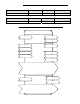
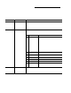
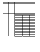
Integration – Global Commands The following figure shows which objects from the thermostat can be monitored and commanded from the BAS front-end.
Integration – Graphic User Interface (GUI) Objects The following objects should be typically used in a GUI: nvoSpaceTemp occupied_heat (nciSetpts); unoccupied_heat (nciSetpts); occupied_cool (nciSetpts); unoccupied_cool (nciSetpts); nvoOutdoorTemp nvoEffectOccup heat_output_primary (nvoUnitStatus) cool_output (nvoUnitStatus) fan (nvoSccStatus) cool_1 (nvoSccStatus) cool_2 (nvoSccStatus) heat_1 (nvoSccStatus) heat_2 (nvoSccStatus) Local_RH_level (nvoRHStatus) supply_RH (nvoRHStatus) effect_reset_RH_setpt (nv
Configuration Objects The following SNVT and UNVT should be typically used for configuration purposes: nciCfg1RtuHp; nciSetpoints; nciCfg3RtuHp; nviDaySchedule[0] nviDaySchedule[1] nviDaySchedule[2] nviDaySchedule[3] nviDaySchedule[4] nviDaySchedule[5] nviDaySchedule[6] Wiring Guide Overview For clarity we will use the term “Device” to represent any product with an active Echelon network connection, including Viconics and non-Viconics controllers.
Maximum Number Of Devices Up to 64 transceivers are allowed per network segment.
Maximum Cable Length The maximum length of a chain is related to its transmission speed. Using proper cable, Echelon supports a baud rate of 78 kilobits per second for distances up to 1600-ft (500 m) in free topology and 8800 ft (2700 m) in bus topology with double terminations. If you require a maximum network length of more than 1600-ft (500 m) or 8800 ft (2700 m), then a repeater is required to extend the network.
Network Adapter Although network connections are polarity insensitive, it is good practice to keep polarity consistent throughout the entire site. Figure 4 shows a network connection example and the location of the Status LED. This Status LED may help to troubleshoot network problems. Figure 4: Network connections and location of the Status LED on a LON module Table 2 shows the different possibilities with the Status LED behavior of the LON module.
Device Identification An Echelon device has a unique mechanism to identify itself, the Neuron ID, which is obtained during commissioning. There are two ways of getting the Neuron ID: with a Service Pin or manually. Service PIN The Service PIN is used to identify the device at commissioning.
Manual Identification Neuron ID of a device can also be entered manually through a commissioning or service tool. Neuron ID should be located on the Echelon chip of the device being commissioned. Figure 8 shows an example of a Manual Neuron ID request made through a commissioning tool.