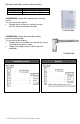
PIR Ready VT76x7 Series With & Without Local Schedule & With Humidification & Dehumidification Strategy Terminal Equipment Controllers Installation Guide For Commercial HVAC Applications rd May 3 , 2012 / 028-0229-R4 CONTENTS Installation April 26, 2011 / 028-0190-R6 Location Installation May 5, 2011 / 028-0228-R3 Theory of operation Features overview Model Chart Network ready Terminal, Identification and Function Wiring Screw terminal arrangement Typical applications Remote humidity sensor accessories Co
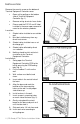
I NSTALLATION Remove the security screw on the bottom of Terminal Equipment Controller cover. Open unit by pulling on the bottom side of Terminal Equipment Controller (fig. 1). Remove wiring terminals from sticker. Please read the FCC ID and IC label installed in the cover upon removal of cover for the wireless products. Location 1. Should not be installed on an outside wall. 2. Must be installed away from any direct heat source. 3. Should not be installed near an air discharge grill. 4.
11. Gently push excess wiring back into hole (fig. 3). 12. Re-Install wiring terminals in their correct locations (fig. 3). 13. Re-install the cover (top side first) and gently push extra wire length back into the hole in the wall. 14. Install security screw. If replacing an existing Terminal Equipment Controller, label the wires before removal of the Terminal Equipment Controller. Electronic controls are static sensitive devices.
Features overview 7 day schedule models, 2 or 4 events Gas/oil or electric system compatibility for all type of applications Remote outdoor sensing capability for added flexibility - System mode lock out - Humidity setpoint reset High limit input to prevent over-humidification Automatic frost protection to prevents costly freeze damage Internal RH sensor and remote RH input with humidification and dehumidification sequence of operation embedded Lockable keypads for tamper proofing
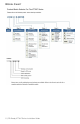
MODEL CHART 5 | PIR Ready VT76x7 Series-Installation Guide
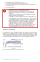
Network ready All Viconics VT76x7 series Terminal Equipment Controllers are designed for stand-alone (Network Ready) operation. They can be fully integrated into your choice of automation systems using the available communication adapter options.
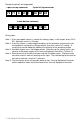
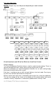
Screw terminal arrangement 3 pole left top connector 5 pole left top connector Y2 Y1 G RC C RH W1 W2 8 pole bottom connector HM AU DH DI HS Scom OS HL Wiring notes: Note 1: If the same power source is used for the heating stages, install jumper across RC & RH. Maximum current is 2.0 amps. Note 2: If auxiliary output is used to toggle occupancy of the electronic control card inside the equipment, configure the relay parameter (Aux cont ) to the N.O. setting.
TYPICAL APPLICATIONS 8 | PIR Ready VT76x7 Series-Installation Guide
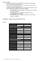
Remote humidity sensor accessories Model no. VH2020W1000 VH2020D10000 Description Wall mounted humidity sensor Duct mounted humidity sensor VH2020W1000, remote wall mounted room humidity sensor. This sensor can be used for: Remote return or room air humidity sensing with the sensor mounted on the wall. VH2020W1000 VH2020D1000, remote duct mounted humidity sensor c/w junction box. This sensor can be used for: Remote return air humidity sensing with the sensor mounted on the return air duct.
User menu flow chart: NOTE: Prompts may not all be present depending on model selected MENU T e mp e r a t s e t ? Y/ N If status is: Unoccupied Ov e r r i d e s c h d Y/ N If status is: Temporary Occupied Time, Occupied hold or Unoccupied hold Re s u me s c h d Y/ N Hu mi d i t y s e t ? Y/ N S y s mo d e s e t ? Y/ N Off Heat Cool Auto F a n mo d e s e t ? Y/ N On stand-alone models only Sc h e d ul e s e t ? Y/ N Cl o c k s e t ? Y/ N On Smart Auto Hu mi d i f i s e t ? Y/ N RH% RH% Ex
Sequence of auto-scroll status display: ROOM CLOCK SYSTEM TEMP & RH STATUS MODE x.x °C or °F XX % RH Monday 12:00 AM Sys mode auto Sys mode off Sys mode heat Sys mode cool Sys mode emergency SCHEDULE STATUS Occupied Occupied hold Unoccup OUTDOOR TEMPERATURE Outdoor x.x °C or°F ALARMS Service Frost ON SetClock Filter Fan lock Outdoor air temperature Outdoor air temperature display is only enabled when outdoor air temperature sensor is connected.
Three status LEDs on the Terminal Equipment Controller cover are used to indicate the status of the fan, a call for heat, or a call for cooling.
Local keypad interface Each of the sections in the menu is accessed and configured using 5 keys on the Terminal Equipment Controller cover. The priority for the alarms is as follows: The YES key is used to confirm a selection, to move onto the next menu item and to manually scroll through the displayed information. The NO key is used when you do not desire a parameter change, and to advance to the next menu item. Can also be used to toggle between heating and cooling setpoints.
Occupied setpoints adjustments There is a default profile set in the Terminal Equipment Controller from the factory. This enables the Terminal Equipment Controller to operate as a non-scheduling unit in day mode operation at start up.
C) Temperature setpoints Permanent setpoint changes Temperat set Y/N This menu permits the adjustment of all permanent temperature setpoints (occupied and unoccupied) as well as the desired temperature units (°F or °C). Permanent setpoints are written to RAM and EEPROM. Cooling Heating setpoint setpoint Occupied mode Occupied mode Cooling set? Y/N Cooling 70.0 °F No next Yes down Use ▲▼ To set value Heating set? Y/N Heating 68.
50% RH and the dehumidification setpoint is changed from 70% RH to 45% RH, the humidification setpoint will be modified to 45% RH by the Terminal Equipment Controller. Humidification process Humidification process will only be allowed when the Terminal Equipment Controller is in heating mode (System Mode = Heat or System Mode = Auto and effective mode at the Terminal Equipment Controller is heat).
E) System mode setting Sys mode set Y/N This menu is accessed to set system mode operation Use ▲▼ to set value, Yes key to confirm Sys mode auto Sys mode cooling Sys mode heating Sys mode emergency Sys mode off Automatic mode Automatic changeover mode between heating and cooling operation Cooling mode Cooling operation mode only Heating mode Heating operation mode only Emergency heat mode ( heat pump models only ) Forced auxiliary heat operation mode only Off mode Normal cooling or heating operation disab
Monday timer Schedule set Tuesday timer Schedule set Wednesday timer Schedule set No next No next Tuesday Wednesda Yes down Yes down set? Y/N set? Y/N Yes key to access day scheduling, No key to jump to next day No next No next Occupied Occupied Occupied Yes down Yes down Day? Y/N Day? Y/N Day? Y/N Yes key to access day scheduling, No key to jump to next day Yes next Copy Y/N Copy Y/N Previous Previous No down No next Yes down Selects the day to be scheduled or modified No next
** To schedule a day as occupied for 24 hours, set that day Occupied time to 12:00 AM and Unoccupied time to 11:59 PM There will be a 1 minute unoccupied period every night at 11:59 PM with this schedule configuration. H) Schedule set (4 events) Schedule set Y/N This section of the menu permits the user to set the whether 2 or 4 events is needed. Each day can be tailored to specific schedules if needed. 4 events can be scheduled per day. Occupied & Unoccupied periods can be set for each day.
* Scheduling events to the same time will cancel the last period and leave the Terminal Equipment Controller in unoccupied mode Ex.
Enabling a permanent occupied or permanent unoccupied schedule hold will cancel any active override. The use of temporary setpoints during permanent hold is permitted. The duration of the temporary setpoint is as set per the TOccTime parameter. Ex. 3 hours Use ▲▼ to set value, Yes key to confirm Schedule resume Resume regular scheduling cancels the permanent hold and re-enables the regular scheduling as set per internal scheduling or as per remote NSB via one of the DI’s configured as remote NSB.
CONFIGURATION PARAMETERS DEFAULT VALUE SIGNIFICANCE AND ADJUSTMENTS PswrdSet Configuration parameters menu access password Default value = 0 No password prompted This parameter sets a password access to prevent unauthorized access to the configuration menu parameters. A default value of “0” will not prompt a password or lock the access to the configuration menu.
Channel Channel selection Default value = 10 Range is: 10 to 26 Conditional parameter to Wireless models (VT76xxX5x00W) This parameter will only appear when a wireless network adapter is present.
DI 1 None, No function will be associated with the input Digital input no.1 configuration Rem NSB, remote NSB timer clock input. Will disable the internal scheduling of the Terminal Equipment Controller. The scheduling will now be set as per the digital input. The time is still displayed as information, but the menu part related to scheduling is disabled and no longer accessible.
Lockout Keypad lockout levels Default value = 0 No lock 0 = No lock 1 = Low level 2 = High level 0 1 2 Pwr del Power-up delay Default value = 10 seconds Frost pr Frost protection enabled Default value = Off Permanent hold Clock setting Schedules setting Fan mode setting System mode setting Temporary setpoints using arrows Permanent Occupied and Unoccupied Setpoints Resume/ Override scheduling LEVEL USER KEY FUNCTIONS On initial power up of the Terminal Equipment Controller (each time 24 VAC po
Pband Proportional Band setting Default value 2 = 2.0 °F ( 0.6 °C ) Adjust the proportional band used by the Terminal Equipment Controller PI control loop. Note that the default value of 2.0 °F ( 1.1 °C ) gives satisfactory operation in most normal installation cases. The use of a superior proportional band different than the factory one is normally warranted in applications where the Terminal Equipment Controller location is problematic and leads to unwanted cycling of the unit.
Heat cph Heating stages cycles per hour Default value = 4 C.P.H. Will set the maximum number of heating stage cycles per hour under normal control operation. It represents the maximum number of cycles that the equipment will turn ON and OFF in one hour. Note that a higher C.P.H will represent a higher accuracy of control at the expense of wearing mechanical components faster. 3, 4, 5, 6,7 & 8 C.P.H.
TOccTime Default value = 3 hours Temporary occupancy time with occupied mode setpoints when override function is enabled When the Terminal Equipment Controller is in unoccupied mode, function is enabled with either the menu or DI1 or DI2 configured as remote override input. 0,1, 2, 3, 4, 5, 6, 7, 8, 9, 10, 11 & 12 hours Cal RS Room air temperature sensor calibration Default value = 0.0 °F or °C Offset that can be added/subtracted to actual displayed room temperature ± 5.0 °F ( ± 2.
C stage Number of cooling stages 2 stages model only Default value = 2 stages Will revert the operation of 2 stage Terminal Equipment Controller to single stage operation only when the second cooling step is not needed. 1 or 2 stages For heat pump models, HP stage selects the number of compressor stages H lock Outside air temperature heating lockout Default value = 120 °F ( 49 °C ) Disables heating stage operation based on outdoor air temperature.
Aux cont Auxiliary contact configuration Default value = N.O. normally open This contact can be used to energize peripheral devices such as: lighting equipment, exhaust fans, economizers, etc. This contact will operate in parallel with the internal occupied/unoccupied schedule of the Terminal Equipment Controller or the remote NSB contact if DI1 or DI2 is used. When the system is in OFF mode, the contact will remain in its unoccupied status independently of the occupied / unoccupied schedule. Configured N.
RH HT Maximum outdoor air temperature for RH setpoint reset. Reset RH higher outside Only valid if an outdoor air sensor is connected at the Terminal temperature setpoint Equipment Controller or a network value is transmitted to the Default value = 32°F Terminal Equipment Controller. See RH LT & RE Sp (0°C) From 20°F up to 55°F (-6.5°C to 13°C) HL SP High humidity limit in the supply.
RE SP The RH setpoint will be reset from the user setpoint to this value Reset humidity when the RH LT outside air temperature value is reached. setpoint Only valid if an outdoor air sensor is connected at the Terminal Default value = Equipment Controller or a network value is transmitted to the 20% RH Terminal Equipment Controller. See RH LT & RE HT. From 10% RH up to 90% RH RH cal Offset that can be added/subtracted to actual displayed humidity by ± Humidity sensor 15.0 %RH.
Wrong mode selected Terminal Equipment Controller in Unoccupied mode Anti-cycle delay active Terminal Equipment Controller will not call for heating Heating setpoint is satisfied Heating lockout attained Wiring error Wrong mode selected Terminal Equipment Controller in Unoccupied mode Anti-cycle delay active Terminal Equipment Controller will not call for cooling Cooling setpoint is satisfied Cooling lockout attained Wiring error Wrong mode selected The Terminal Equipment Controller will not turn on
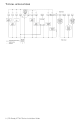
HUMIDITY CONTROL Humidity reset Humidity setpoint reset by outside air temperature 45% RH Set = 45% %RH Setpoint 40% RH HT = 32°F 35% 30% 25% RE Sp = 20% 20% RH LT = -20°F -40°F -20°F 0°F 20°F Outside Air Temp. 40°F Fig.
S PECIFICATIONS Terminal Equipment Controller power requirements: Operating conditions: Storage conditions: Temperature sensor: Resolution: Control accuracy: Humidification setpoint: Dehumidification setpoint: Contact output rating: Humidification analog output rating: Humidification analog output accuracy Occ, Stand-By and Unocc cooling setpoint range: Occ, Stand-By and Unocc heating setpoint range: Room and outdoor air temperature display range: Proportional band for room temperature control: Digital in
DRAWING & DIMENSIONS Viconics Technologies Inc. Tel.: Fax: Toll free: www.viconics.