Device Replacement Procedure VT8000 Series Room Controllers
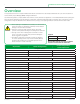
VT8000 Controller Replacement Guide 2 Overview This procedure shows how to replace VT8000 Series Room Controllers which are already installed and set-up to communicate with a front end Multi-purpose Manager (MPM) via Zigbee or BACnet. Use the following table to compare default values with the current parameter configurations on the VT8300/VT8350 before replacing the Room Controller.
VT8000 Controller Replacement Guide 3 Object Name Default Configurations Temporary Occupancy Time 2H Dehumidification Hysteresis 5% Dehumidification Max Cooling 100% Dehumidification Lockout Enabled Current Configurations before Replacement 4/7 Configuration CPH 4 Control Type Floating BO8 Out Time 15 Minute BO8 AuxOut Not Used Floating Time 1.5 min DA /RA DA 5/7 Configuration Proportional Band 3°F (1.
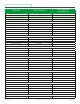
VT8000 Controller Replacement Guide 4 Object Name Default Configurations Units (Temperature Scale) °C Low Backlight 60% Night Backlight 5% RH display Enabled Current Configurations before Replacement The below parameters are not accessible through the Setup menu in the VT8300/VT8350. However, they can be modified via the front end Room Controllers once the device is online.
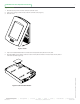
VT8000 Controller Replacement Guide 5 ZigBee Network 1. Remove security screw on bottom of Room Controller cover. 2. Open unit by pulling on bottom side of Room Controller cover (Figure 1). 3. Remove cover. Figure 1 Cover Figure 2 Communication Module Viconics Technologies Inc. 028-0454-00 | 9245 Langelier Blvd. | St.-Leonard | Quebec | Canada | H1P 3K9 www.viconics.com | sales@viconics.com | Tel: (514) 321-5660 | Fax: (514) 321-4150 November 2014 © 2014 Viconcis Technologies.
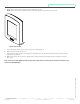
VT8000 Controller Replacement Guide 6 6. Mount the front plate on the existing back plate installed on the wall. NOTE: Ensure small plastic projections at top of front plate align with notches at top of back plate. Figure 3 Secure Unit 7. Push on front plate bottom two corners to secure unit in place (Figure 3). 8. Wait for Room Controller to power up. 9. Use the table on earlier pages to re-configure your parameters such as sequence of operation, pipe number, occupied heating/cooling setpoints. 10.
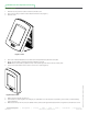
VT8000 Controller Replacement Guide 7 BACnet Network 1. Remove security screw on bottom of Room Controller cover. 2. Open unit by pulling on bottom side of Room Controller cover (Figure 1). 3. Remove cover. Figure 1 Cover Figure 2 Secure Unit 7. Wait for Room Controller to power up. 8. Use the table on earlier pages to re-configure your parameters such as sequence of operation, pipe number, occupied heating/ cooling setpoints. 9.