VT8300 User Interface Guide VT8300 Room Controller Series Commercial and Hotel/Lodging HVAC Fan Coil Applications CONTENTS HMI Display How to Enter Setup Screen Setup Screen Display Schedule Menu Clock Settings Schedule Settings Occupancy Settings Wireless Ecosystem Settings LUA Settings Network Settings ZigBee® Network Settings BACnet® Network Settings BACnet® Instance Number Configuration Parameters Password Settings Setpoints Settings Display Settings User HMI - Hospitality User HMI - Commercial Oth
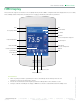
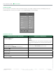
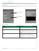
User Interface Guide VT8300 Series HMI Display The below shows a typical user interface for the hospitality industry. The User HMI is configurable and allows display functions such as Date, Time, Humidity, Outdoor Temperature, and Setpoint to be enabled or disabled by setting various parameters.
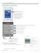
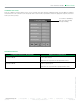
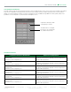
User Interface Guide 3 VT8300 Series Enter Set-up Screen Touch and hold this point for 3 seconds to enter setup mode Note: If a configuration/installer password is activated to prevent unauthorised access to the configuration menu parameters, a password entry prompt shows to prevent access to device configuration components.
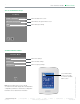
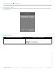
User Interface Guide VT8300 Series SET-UP SCREEN DISPLAY 2/2 2/ 2 Set u p Cl o ck - Sch ed u le Enter Schedule menu screen Wi rel ess Eco sy s t e m Enter Wireless Ecosystem menu screen LUA Enter LUA script settings SCHEDULE MENU SCREEN Clock Enter Clock settings Sch ed u l e Enter Schedule settings Occu p an cy Enter Occupancy settings Touch and hold this point for 3 seconds to enter the Schedule Menu screen.
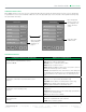
User Interface Guide 5 VT8300 Series CLOCK SETTINGS The Clock settings screen allows the device’s internal time settings to be changed, including current time, standard day, month, year and weekday options, as well as choice between a 12 hour AM / PM display or a 24 hour display. Cl oc k Time F or m a t Time AM - P M --:-- Ye a r 2014 Month J a n.
User Interface Guide VT8300 Series SCHEDULE SETTINGS There are 7 different schedule setting screens, one for each day of the week, titled accordingly. Each day can have different scheduled events where the room controller is set to Occupied status or back to Unoccupied status and use the appropriate setpoints, back and forth up to 3 times per day.
User Interface Guide 7 VT8300 Series OCCUPANCY SETTINGS The occupancy settings screen allows you to determine how the Room Controller will determine whether it is functioning in Occupied or Unoccupied mode. Oc c u p a n c y O cc u p a n c y c md . L o c o c c . PARAMETER DETAILS Configuration Parameters Default Value Significance and Adjustments Occupancy Command Occupancy cmd Default value: Local occ Loc occ: occupancy is determined by local sequences. Occupied: force occupied mode.
User Interface Guide VT8300 Series WIRELESS ECOSYSTEM When ZigBee wireless sensors are set up to communicate with a Room Controller, the functioning of each such sensor is described in a separate Zone screen, up to a maximum of 10 Zones. Select the appropriate type of sensor based on the required functioning using the up and down arrow keys.
User Interface Guide 9 VT8300 Series LUA SETTINGS The LUA settings screens show information about any custom LUA script uploaded to the controller. LUA scripts are not programmable on the controllers, and so must be uploaded to the controllers. 1/3 LUA 2/3 LUA LU A p ro g r a m ’s n a m e : U ser p ro g r a m The title of the LUA script is shown here P ro g r a m : if not init then init=true delay=0 end i f ME . B V1 = = 1 t h e n ME .
User Interface Guide VT8300 Series LUA GENERIC PARAMETERS The LUA settings include six generic parameters that do not have predefined values. These can be used to represent LUA script variables. They are user configurable in their default state, but when they are assigned a value by a LUA script they become read only, and the display colour of the parameter changes to red. These parameters are also modifiable through BACnet as Analog Values (AVs).
User Interface Guide 11 VT8300 Series ZIGBEE PRO NETWORK SETTINGS ZigBee Pro set-up screen shows when a ZigBee card is detected in the model. Select the desired parameter and use the up or down arrow to set the parameter to the desired value. 1/2 Z ig Bee Netwo r k Co m ad d r ess 254 Zig Bee P an ID 0 Zig Bee ch an n el 10 Zig Bee sh o r t 0x0000 IEE E ad d r ess 0x0000 Zig Bee statu s No NWK Previous Page Next Page ZigBee® Pro short address.
User Interface Guide VT8300 Series PARAMETER DETAILS Configuration Parameters Default Value Significance and Adjustments ZigBee Pro PAN ID ZigBee Pan ID Personal Area Network Identification Default value = 0 Range value = 0 - 1000 Links specific Terminal Equipment Controllers to specific ZigBee® Pro coordinators. For every Terminal Equipment Controller reporting to a coordinator. Ensure set the SAME channel value both on the coordinator and the Terminal Equipment Controller(s).
User Interface Guide 13 VT8300 Series 2/2 ZigBee others Door status if installed Window status if installed Battery status of wireless switch D o o r status Closed D o o r installed No Win d o w status Closed Win . installed No B at t ery alarm Off Perm it join On Indicates if door contact is installed Indicates if window contact is installed Automatically allows ZigBee® Pro devices to join the network through this controller.
User Interface Guide VT8300 Series BACNET NETWORK SETTINGS BACnet network set-up screen shows when BACnet is detected in model. Select desired parameter and use up or down arrow to set parameter to desired value. 1/2 B ACnet network Imperial or Metric units Baud rate settings C O M ad dress 254 N et w o rk units SI N et w o rk lang. English B au d rate Auto B A C n et status Offline 254 value sets BACnet® network Offline.
User Interface Guide 15 VT8300 Series BACNET INSTANCE NUMBER The default BACnet® instance number is generated by the model number and COM address of the controller. For example, The instance number of a VT8300A5B00 with a COM address of 57 is generated as “83057”. The default instance number appears first. To change the instance number, use number pad and press Accept and save. Press Reset to automatic instance addressing to reset to automatic instance addressing.
User Interface Guide VT8300 Series CONFIGURATION PARAMETERS SCREEN 1//7 1/7 Configuration U I 16 None U I 17 None U I 19 None O ccupancy src Motion Sm art recovery Off Set point func. Attach Stp PARAMETER DETAILS Configuration Parameters Default Value Significance and Adjustments Universal Input No. 1 UI 16 Universal input no.1 configuration Default value = None None: no function associated with input Rem NSB: remote NSB timer clock input.
User Interface Guide 17 VT8300 Series PARAMETER DETAILS SCREEN 1/7 Configuration Parameters Default Value Significance and Adjustments Universal Input No. 3 UI 19 Universal input no.3 configuration Default value = None None: no function associated with input though input can be used for remote network monitoring. COC/NH: change over dry contact. Normally heat used for hot/cold water or air change over switching in 2 pipe systems. COC/NC: change over dry contact.
User Interface Guide VT8300 Series CONFIGURATION PARAMETERS SCREEN 2/7 2/7 Configuration M o de button Normal A u to mode Enabled F an menu On-Auto A u to fan func. AS St andy mode Abs St andby diff. 2.
User Interface Guide 19 VT8300 Series PARAMETER DETAILS SCREEN 2/7 Configuration Parameters Default Value Significance and Adjustments Standby Mode Standby mode Default value: Abs Choose which standby setpoints are used for control. Abs: absolute Standby entered values are used for standby mode. Offset: offset Occupied setpoints +/- Standby diff. used for standby mode. Standby Difference Standby diff.
User Interface Guide VT8300 Series CONFIGURATION PARAMETERS SCREEN 3/7 3/7 Configuration St andby time 0.5 hrs U n occ. time 0.0 hrs Temp. occ. time 2.0 hrs D eh hysteresis 5.0% RH D eh. max cool 100% D eh. lockout Enabled These parameters are only displayed on models with built in humidity sensor PARAMETER DETAILS SCREEN 3/7 Configuration Parameters Default Value Significance and Adjustments Standby Time Standby time Default value: 0.
User Interface Guide 21 VT8300 Series PARAMETER DETAILS SCREEN 3/7 Configuration Parameters Default Value Significance and Adjustments Temporary Occupancy Time Temp. occ. time Default value: 2 hours Temporary occupancy time with occupied mode setpoints when override function is enabled. When Terminal Equipment Controller is in unoccupied mode, function is enabled with either the menu or UI2 configured as remote override input. Range: 0 - 24 hours. Humidity Control Hysteresis Deh.
User Interface Guide VT8300 Series CONFIGURATION PARAMETERS SCREEN 4/7 4/7 Configuration C PH 4 C o ntrol Type Floating B O 8 Out Time 15 min B O 8 AuxOut Not used F lo a ting Time 0.5 min D A / RA DA PARAMETER DETAILS SCREEN 4/7 Configuration Parameters Default Value Significance and Adjustments Cooling Output Cycles/Hr CPH Default value: 4 CPH Sets maximum number cycles per hour under normal control operation.
User Interface Guide 23 VT8300 Series PARAMETER DETAILS SCREEN 4/7 Configuration Parameters Default Value Significance and Adjustments Reheat Output Time BO8 Out Time Default value: 0 = 15 minutes Sets reheat output time base. Valid only if reheat sequences are enabled. 0 = 15 minutes 1 = 10 seconds for solid state relays BO8 AuxOut Aux contact function used for reheat if sequence is set to use BO8 for reheat through network or local. Ignore this parameter.
User Interface Guide VT8300 Series CONFIGURATION PARAMETERS SCREEN 5/7 5/7 Configuration Prop. band 3.0 Pip e no. 2 Seq. operation Heat only Pu rge sample 0.0 hrs Pu rge open 1 min PARAMETER DETAILS SCREEN 5/7 Configuration Parameters Default Value Significance and Adjustments Proportional Band Setting Prop. band Default value: 3 Adjusts proportional band used by the Terminal Equipment Controller PI control loop. Note: default value of 3.
User Interface Guide 25 VT8300 Series PARAMETER DETAILS SCREEN 5/7 Configuration Parameters Default Value Significance and Adjustments Pipe Setting Type Installed Pipe no. Default value: 4 pipes Defines type of system installed. 2 Pipes: limits number of sequences of operation available from 0 - 4. It also enables heat/cool operation from the same output. 4 Pipes: can access all sequences of operation from 0 - 2. Also enables heat/cool operation from different output. Sequence Operation Seq.
User Interface Guide VT8300 Series CONFIGURATION PARAMETERS SCREEN 6/7 6/7 Configuration M ain password 0 U se r password 0 Schedule menu Enabled C al ib. temp. 0.0 C C al ib. humid. 0% RH Parameter only displayed on models with built in humidity sensor. PARAMETER DETAILS SCREEN 6/7 Configuration Parameters Default Value Significance and Adjustments Main Password Main password Default value: 0 Installer password.
User Interface Guide 27 VT8300 Series CONFIGURATION PARAMETERS SCREEN 7/7 7/7 Reinitialization Erase all? No A re you sure? No Pu sh to accept: PARAMETER DETAILS SCREEN 7/7 Configuration Parameters Default Value Erase All Erase all? Default value: No | 9245 Langelier Blvd. | St.-Leonard | Quebec | Canada | www.viconics.com | sales@viconics.com H1P 3K9 | Tel: (514) 321-5660 | © 2014 Viconics Technologies Inc. All rights reserved.
User Interface Guide VT8300 Series PASSWORD SETTINGS The following shows you how to enter the password for the Installer and User Installer Password Installer Password . . . . Enter your password 0 1 2 3 4 5 6 7 8 9 Reset 2. 3. 4. Installer password prompt shows only if password value is greater than 0000. A password value of 0000 disables installer password but does not restrict access to configuration options.
User Interface Guide 29 VT8300 Series User Password User Password . . . . Wrong code 1. 2. 3. 4. 0 1 2 3 4 5 6 7 8 9 User password prompt shows only if password value is greater than 0000. A password value of 0000 disables user password but does not restrict access to local user functions. User password prompt automatically disappears after 10 seconds if no value is entered. User is permitted access to controller interface to change any allowed settings when correct password is entered.
User Interface Guide VT8300 Series SETPOINT SETTINGS 1/2 1/2 Setpoints U n occ. cool. 26.5 °C St a ndby cool. 25.5 °C O cc . cool. 24.0 °C O cc . heat. 22.0 °C St a ndby heat. 20.5 °C U n occ. heat. 16.5 °C SETPOINT PARAMETER DETAILS Configuration Parameters Default Value Significance and Adjustments Unocc. cool. Default value: 26.5 °C (80 °F) Unoccupied Cooling Standby cool. Default value: 25.5 °C (78 °F) Standby Cooling Unoccupied cooling setpoint range: 12.0 to 37.
User Interface Guide 31 VT8300 Series SETPOINT SETTINGS 2/2 2/2 Setpoints D efault heat 22.0 °C M in. deadband 1.5 °C M ax. heating 32.0 °C M in. cooling 12.0 °C D ehumidify 50.0 %RH Parameter only displayed on models with built in humidity sensor. SETPOINT PARAMETER DETAILS Configuration Parameters Default Value Significance and Adjustments Default Heat Default heat Default value: 22.0 °C (73 °F) Used for hospitality applications in stand-alone mode only.
User Interface Guide VT8300 Series DISPLAY SETTINGS 1/2 1/2 Display U ser HMI 0 C o lor White M ain display Temp. St andby screen No SETPOINT PARAMETER DETAILS Configuration Parameters Default Value Significance and Adjustments User HMI User HMI Default value: 0 Select user HMI type. Range: 0 to 11. Color Default value: White White Main display Default value: Temp. Main Display Standby screen Default value: No Standby Screen Change text colors according to set font colors.
User Interface Guide 33 VT8300 Series User HMI for Hospitality 0 (Hospitality) • • • • • • 1 (Hospitality) • • • • Setpoint adjustment System mode setting Fan mode setting Local unit scale adjustment Local user language User help menu 2 (Hospitality) • Setpoint adjustment System mode setting Fan mode setting User help menu • • 3 (Hospitality) Local unit scale adjustment Local user language User help menu • • Setpoint adjustment User help menu Parameters are model dependent and may not appear
User Interface Guide 8 (Commercial) 9 (Commercial) • • • • • • Setpoint adjustment Unoccupied mode override Local user language User help menu • 10 (Commercial) Setpoint adjustment Unoccupied mode override User help menu • • • VT8300 Series 11 (Commercial) • • • Setpoint adjustment Unoccupied mode override User help menu • Setpoint adjustment System mode setting Unoccupied mode override User help menu Note: The day/night setback button appears only in unoccupied mode from 7 to 11 in HMI
User Interface Guide 35 VT8300 Series Heating only Configuration Time and Date show only when a network time synchronisation command is received. Setpoint value shows if main display parameter is set to Setpoint. On/Off icon is used instead of system mode icon when sequence of operation is set to either heating on or cooling only. Setpoint Adjustment for Cooling Mode In Cooling mode, the setpoint displayed in the bar is the current occupied cooling setpoint.
User Interface Guide VT8300 Series Setpoint Adjustment for Heating Mode In automatic mode, setpoint showing at the top of the set point bar located directly under the blue line represents the actual occupied cooling setpoint. During occupied setpoints adjustment, large digits are temporarily used to display the occupied Cooling Setpoint or occupied Heating Setpoint. The actual setpoint is dependent on the last effective demand (heating or cooling).
User Interface Guide 37 VT8300 Series CUSTOMIZABLE COLOR OPTIONS Green Brown Grey Viconics Technologies Inc. 028-0427-01 | 9245 Langelier Blvd. | St.-Leonard | Quebec | Canada | www.viconics.com | sales@viconics.com Blue H1P 3K9 | Tel: (514) 321-5660 | © 2014 Viconics Technologies Inc. All rights reserved.
User Interface Guide VT8300 Series DISPLAY SETTINGS 2/2 2/2 Display L anguage English U n i ts °C L o w backLight 60% N ight backLight 5% R H display Disabled Parameter only displayed on models with built in humidity sensor. SETPOINT PARAMETER DETAILS Configuration Parameters Default Value Significance and Adjustments Language Language Default value: English Select language for main display.
User Interface Guide 39 VT8300 Series SERVICE SCREEN VIEWS The service view screens show the current status of certain points locally at the controller. These points can also be viewed through the network. Service view allows service contractor to visualize the status of key functionality to correctly diagnose operational system issues. 1/6 Service view F irm w are rev. 1.0 Firmware Revision R o o m t em p . xx.x °C Room Temperature C h g O ver t em p . xx.
User Interface Guide VT8300 Series 3/6 Service view U I16 st at u s Not activ Universal Input Status U I17 st at u s Not activ Universal Input Status U I19 st at u s Activated Universal Input Status Win d o w alarm Off Window Alarm Status Service alarm Off Service Alarm Status F ilt er alarm Off Filter Alarm Status L o cal m o t io n On Local Motion Status D eh . st at u s Off Dehumidification Status Parameter only displayed on models with built in humidity sensor.
User Interface Guide 41 VT8300 Series 5/6 Service view U O 9 C o n f ig Binary Universal Output Configuration U O 10 C o n f ig Binary Universal Output Configuration U O 11 C o n f ig Binary Universal Output Configuration U O 12 C o n f ig Binary Universal Output Configuration 6/6 Service view D evice n am e: The Model Number is the BACnet® device name automatically assigned when using the current BACnet® addressing scheme based on the MAC address.
User Interface Guide VT8300 Series TEST OUTPUTS 1/2 Test Outputs B O 4 Fan High Off B O 3 Fan Med Off B O 2 Fan Low Off B O 8 Aux Output Off Note 1: Cooling output can also be used for heating on two pipes systems. Note 2: The test output screen allows manual override of specified outputs. When any BACnet® network priority array includes a value, the status background shows in red.
User Interface Guide 43 VT8300 Series TEST OUTPUTS CASE A CASE B 2/2 Test o u t p u t s 2/2 Test outputs UO 9 B in ary Off UO11 Analog 0 Vdc U O 10 B in ary Off UO12 Analog 0 Vdc UO 11 B in ary Off UO 12 B in ary Off Note: screen Test outputs are LIVE. Any output gets displayed immediately for any value change according to the following: 1. If any BACnet priority array (1 - 16) includes a value, the displayed state background shows in red. 2.
User Interface Guide VT8300 Series LANGUAGE SELECTION Language selection F r en c h Enabled S p an i s h Enabled Chinese Enabled Russian Enabled Viconics Technologies Inc. 028-0427-01 | 9245 Langelier Blvd. | St.-Leonard | Quebec | Canada | www.viconics.com | sales@viconics.com H1P 3K9 | Tel: (514) 321-5660 | © 2014 Viconics Technologies Inc. All rights reserved.
User Interface Guide 45 VT8300 Series APPENDIX A: TERMINAL CORRESPONDENCE The terminals of an VT8300 are identified differently and have a wider range of possible functions compared to those of any of the VT7000 series Room Controllers. Nonetheless, there is a direct correspondance of functions between the terminals of the VT7000 series and the VT8300 series. Consult the table below to verify the appropriate terminal when replacing a VT7000 Room Controller with a VT8300 Room Controller.