VT8600 Series User Interface Guide VT8600 Room Controller Series Rooftop Unit and Indoor Air Quality Controller
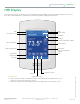
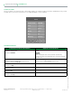
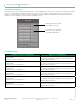
User Interface Guide 2 VT8600 Series HMI Display The below shows a typical user interface for the hospitality industry. The User HMI is configurable and allows display functions such as Date, Time, Outdoor Temperature, and Setpoint to be enabled or disabled by setting various parameters.
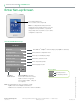
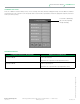
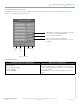
User Interface Guide VT8600 Series 3 Enter Set-up Screen Touch and hold this point for 3 seconds to enter setup mode Note: If a configuration/installer password is activated to prevent unauthorised access to the configuration menu parameters, a password entry prompt shows to prevent access to device configuration components.
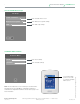
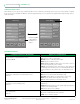
User Interface Guide 4 VT8600 Series SET-UP SCREEN DISPLAY 2/2 2/ 2 Set u p Cl o ck - Sch ed u le Enter Schedule menu screen Wi rel ess Eco sy s t e m Enter Wireless Ecosystem settings LUA Enter LUA script settings SCHEDULE MENU SCREEN Clock Enter Clock settings Sched u l e Enter Schedule settings Touch and hold this point for 3 seconds to enter the Schedule Menu screen.
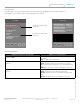
User Interface Guide VT8600 Series 5 CLOCK SETTINGS The Clock settings screen allows the device’s internal time settings to be changed, including current time, standard day, month, year and weekday options, as well as choice between a 12 hour AM / PM display or a 24 hour display. Cl oc k Time For m a t Time AM - P M --:-- Ye a r 2014 Month J a n.
User Interface Guide 6 VT8600 Series SCHEDULE SETTINGS There are 7 different schedule setting screens, one for each day of the week, titled accordingly. Each day can have different scheduled events where the room controller is set to Occupied status or back to Unoccupied status and use the appropriate setpoints, back and forth up to 3 times per day.
User Interface Guide VT8600 Series 7 WIRELESS ECOSYSTEM When wireless sensors are set up to communicate with a room controller, the functioning of each such sensor is described in a separate Zone screen, up to a maximum of 10 Zones. Select the appropriate type of sensor based on the required functioning using the up and down arrow keys.
User Interface Guide 8 VT8600 Series LUA SETTINGS The LUA settings screens show information about any custom LUA script uploaded to the controller. LUA scripts are not programmable on the controllers, and so must be uploaded to the controllers. 1/3 LUA L UA p r o g ram ’s n a m e : User p ro g r a m P ro g r a m : i f no t i n i t t h en init=true d el a y = 0 en d i f M E . B V1 = = 1 t h e n ME.
User Interface Guide VT8600 Series 9 LUA GENERIC PARAMETERS The LUA settings include six generic parameters that do not have predefined values. These can be used to represent LUA script variables. They are user configurable in their default state, but when they are assigned a value by a LUA script they become read only, and the display colour of the parameter changes to red. These parameters are also modifiable through BACnet as Analog Values (AVs).
User Interface Guide 10 VT8600 Series ZIGBEE PRO NETWORK SETTINGS The ZigBee Pro set-up screen shows when a ZigBee card is detected in the model. Select the desired parameter and use up or down arrows to set the parameter to the desired value. 1/2 Z ig Bee Netwo r k Co m ad d r ess 254 Zig Bee P an ID 0 ZigBee ch an n el 10 Zig Bee sh o r t 0x0000 IEE E ad d r ess 0x0000 Zig Bee statu s No NWK Previous Page Next Page ZigBee® Pro short address.
User Interface Guide VT8600 Series 11 PARAMETER DETAILS Configuration Parameters Default Value Significance and Adjustments ZigBee Pro PAN ID ZigBee Pan ID Personal Area Network Identification Default value: 0 Range value: 0 - 1000 Links specific Terminal Equipment Controllers to specific ZigBee® Pro coordinators. For every Terminal Equipment Controller reporting to a coordinator. Ensure set the SAME channel value both on the coordinator and the Terminal Equipment Controller(s).
User Interface Guide 12 VT8600 Series 2/2 Zigbee others Door status if installed Window status if installed Battery status of wireless switch D o o r st atus Closed D o o r in stalled No Win d o w status Closed Win . in stalled No B at t ery alarm Off Perm it join On Indicates if door contact is installed Indicates if window contact is installed Automatically allows ZigBee® Pro devices to join the network through this controller.
User Interface Guide VT8600 Series 13 BACNET NETWORK SETTINGS BACnet network set-up screen shows when BACnet is detected in model. Select desired parameter and use up or down arrow to set parameter to desired value. 1/2 B ACnet network Imperial or Metric units Baud rate settings C O M ad dress 254 N et w o rk units SI N et w o rk lang. English B au d rate Auto B A C n et status Offline 254 value sets BACnet® network Offline.
User Interface Guide 14 VT8600 Series BACNET INSTANCE NUMBER The default BACnet® instance number is generated by the model number and COM address of the controller. For example, The instance number of a VT8600A5B00 with a COM address of 57 is generated as “86057”. The default instance number appears first. To change the instance number, use number pad and press Accept and save. Press Reset to automatic instance addressing to reset to automatic instance addressing.
User Interface Guide VT8600 Series 15 CONFIGURATION PARAMETERS SCREEN 1/9 1/9 Configuration U I 1 6 co n fig No n e U I 1 7 c o n fig No n e U I 1 9 co n fig No n e Oc c u p a n cy cmd Loc occ. S m ar t r ec o ve r y Off S e t p o in t fu n c . Attac h Stp PARAMETER DETAILS SCREEN 1/9 Configuration Parameters Default Value UI 16 Universal input no.1 configuration Default value: None Significance and Adjustments Universal Input No. 1 None: No function will be associated with the input.
User Interface Guide 16 VT8600 Series PARAMETER DETAILS SCREEN 1/9 Configuration Parameters Default Value Significance and Adjustments Universal Input No. 2 None: No function will be associated with the input. Input can be used for remote network monitoring. UI 17 Universal input no.2 configuration Default value: None Door Dry: This configuration is only functional if binary input #1 is set to Motion NO or Motion NC or an onboard PIR sensor is used.
User Interface Guide VT8600 Series 17 CONFIGURATION PARAMETERS SCREEN 2/9 2/9 Configuration F an cont. heat Off F an delay On St andy mode Abs St andby diff. 2.0 °C Po wer-up delay 10 Sec. PARAMETER DETAILS SCREEN 2/9 Configuration Parameters Default Value Fan cont. heat Fan control Default value: On Significance and Adjustments Fan control in heating mode. When selecting On; the Terminal Equipment Controller in all cases will always control the fan (terminal G).
User Interface Guide 18 VT8600 Series PARAMETER DETAILS SCREEN 2/9 Configuration Parameters Default Value Significance and Adjustments Standby mode Standby Mode Default value: Abs Choose which standby setpoints are used for control. Abs: absolute Standby entered values are used for standby mode. Offset: relative Occupied setpoints +/- Standby diff. used for standby mode. Standby diff.
User Interface Guide VT8600 Series 19 CONFIGURATION PARAMETERS SCREEN 3/9 3/9 Configuration St andby time 0.5 hrs U n occ. time 0.0 hrs Temp. occ. time 2.0 hrs PARAMETER DETAILS SCREEN 3/9 Configuration Parameters Default Value Standby time Default value: 0.5 hours Significance and Adjustments Standby Time Time delay between the moment where the PIR cover detects last movement in the area, and the time which the Terminal Equipment Controller stand-by setpoints become active. Range: 0.5 to 24.
User Interface Guide 20 VT8600 Series CONFIGURATION PARAMETERS SCREEN 4/9 4/9 Configuration C o oling CPH 4 H eating CPH 4 F ro st protec. Off B O 1 aux config NO A n t i short cycle 2 min PARAMETER DETAILS SCREEN 4/9 Configuration Parameters Default Value Cooling CPH Cooling stages cycles per hour. Default value: 4 CPH Significance and Adjustments Sets the maximum number of cooling stage cycles per hour under normal control operation.
User Interface Guide VT8600 Series 21 PARAMETER DETAILS SCREEN 4/9 Configuration Parameters Default Value Significance and Adjustments Off: no room frost protection Frost protec Frost protection enabled On: room frost protection enabled in all system mode at: 42 °F ( 5.6 °C ) Default value: Off Frost protection is enabled even in system Off mode Off or On Binary Output Terminal BO1 aux config Default value: NO Output directly follows occupancy of the Terminal Equipment Controller.
User Interface Guide 22 VT8600 Series CONFIGURATION PARAMETERS SCREEN 5/9 5/9 Configuration Prop. band 3.0 H ea t stages 2 C o ol stages 2 Econo. config Off C h ngOvr Sp 13.0 °C M ec h cooling Off PARAMETER DETAILS SCREEN 5/9 Configuration Parameters Default Value Prop. band Default value: 3.0 Significance and Adjustments Proportional Band Setting Adjusts proportional band used by the Terminal Equipment Controller PI control loop. Note: default value of 3.
User Interface Guide VT8600 Series 23 PARAMETER DETAILS SCREEN 5/9 Configuration Parameters Default Value Significance and Adjustments Heat stages Number of heating stages. Applicable to 2 stage models only Default value: 2 stages Will revert the operation of 2 stages Terminal Equipment Controller to single stage operation only when the second heating step is not needed.
User Interface Guide 24 VT8600 Series CONFIGURATION PARAMETERS SCREEN 6/9 6/9 Configuration H ea t lock 49.0 °C C o ol lock -40.0 °C D is charge HL 49 °C D is charge LL 7 °C R eheat lockout 0 °C FA range 0 l/s PARAMETER DETAILS SCREEN 6/9 Significance and Adjustments Heat lock Outside air temperature heating lockout Default value: 120 °F (49 °C) Disables heating stage operation based on outdoor air temperature.
User Interface Guide VT8600 Series 25 CONFIGURATION PARAMETERS SCREEN 7/9 7/9 Configuration Econo. min pos. 0 % Econo. max pos. 100 % M in fresh air 0 l/s M ax fresh air 0 l/s M in CO2 800 ppm M ax CO2 1200 ppm PARAMETER DETAILS SCREEN 7/9 Configuration Parameters Default Value Econo. min pos. Minimum Fresh Air Damper/Economizer Position Default value: 0% Significance and Adjustments Minimum fresh air damper position. Effective only in Occupied mode (Fan is ON).
User Interface Guide 26 VT8600 Series PARAMETER DETAILS SCREEN 7/9 Configuration Parameters Default Value Min CO2 Minimum CO2 Level Default value: 800 ppm Significance and Adjustments Minimum CO2 Level required. Effective only in Occupied mode (Fan is ON). This value is used to determine the fresh air damper position based on the Min/Max CO2 and Min/Max Pos values set. See Fresh Air Damper Position section for more details.
User Interface Guide VT8600 Series 27 CONFIGURATION PARAMETERS SCREEN 8/9 8/9 Configuration M ain password 0 U se r password 0 Schedule menu Enabled C ali b. temp. 0.0 C C ali b. OS temp. 0.0 C PARAMETER DETAILS SCREEN 8/9 Configuration Parameters Default Value Main password Default value: 0 Significance and Adjustments Main Password Installer password. This parameter sets a protective access password to prevent unauthorized access to configuration menu parameters.
User Interface Guide 28 VT8600 Series CONFIGURATION PARAMETERS SCREEN 9/9 9 /9 Reinitialization Erase all? No A re you sure? No Pu sh to accept: PARAMETER DETAILS SCREEN 9/9 Configuration Parameters Default Value Are you sure? Default value: No Viconics Technologies Inc.
User Interface Guide VT8600 Series 29 PASSWORD SETTINGS The following shows you how to set-up the password for the Installer and User Installer Password Installer Password • • • • Enter your password 2. 3. 4. 1 2 3 4 5 6 7 8 9 Installer password prompt shows only if password value is greater than 0000. A password value of 0000 disables installer password but does not restrict access to configuration options.
User Interface Guide 30 VT8600 Series User Password User Password . . . . Wrong code 1. 2. 3. 4. 0 1 2 3 4 5 6 7 8 9 User password prompt shows only if password value is greater than 0000. A password value of 0000 disables user password but does not restrict access to local user functions. User password prompt automatically disappears after 10 seconds if no value is entered. User is permitted access to controller interface to change any allowed settings when correct password is entered.
User Interface Guide VT8600 Series 31 SETPOINT SETTINGS 1/2 1/2 Setpoints U n occ. cool. 26.5 °C St andby cool. 25.5 °C O cc . cool. 24.0 °C O cc . heat. 22.0 °C St andby heat. 20.5 °C U n occ. heat. 16.5 °C SETPOINT PARAMETER DETAILS Configuration Parameters Default Value Significance and Adjustments Unocc. cool. Default value: 26.5 °C (80 °F) Unoccupied Cooling Standby cool. Default value: 25.5 °C (78 °F) Standby Cooling Unoccupied cooling setpoint range: 2.0 to 37.5 °C (54 to 100 °F).
User Interface Guide 32 VT8600 Series SETPOINT SETTINGS 2/2 2/2 Setpoints D ef a ult heat 22.0 °C M in . deadband 1.5 °C M ax. heating 32.0 °C M in . cooling 12.0 °C Su pply air SP 13.0 °C M in sup. heat 18.0 °C SETPOINT PARAMETER DETAILS Configuration Parameters Default Value Default heat Default value: 22.0 °C (73 °F) Significance and Adjustments Default Heat Used for hospitality applications in stand-alone mode only.
User Interface Guide VT8600 Series 33 DISPLAY SETTINGS 1/2 1/2 Display U ser HMI 0 C o lor White M ain display Temp. St andby screen No DISPLAY PARAMETER DETAILS Configuration Parameters Default Value User HMI Default value: 0 Significance and Adjustments User HMI Select user HMI type. Range: 0 to 11. Color Default value: White White Main display Default value: Temp. Main Display Standby screen Default value: No Standby Screen Change text colors according to set font colors.
User Interface Guide 34 VT8600 Series User HMI for Hospitality Hospitality 0 • • • • • • Setpoint adjustment System mode setting Fan mode setting Local unit scale adjustment Local user language User help menu Hospitality 1 • • • • Setpoint adjustment System mode setting Fan mode setting User help menu Hospitality 2 • • • Local unit scale adjustment Local user language User help menu Hospitality 3 • • Setpoint adjustment User help menu Parameters are model dependent and may not appear on cert
User Interface Guide VT8600 Series Commercial 8 • • • • Setpoint adjustment Unoccupied mode override Local user language User help menu 35 Commercial 9 • • • Setpoint adjustment Unoccupied mode override User help menu Commercial 10 • • • Setpoint adjustment Unoccupied mode override User help menu Commercial 11 • • • • Setpoint adjustment System mode setting Unoccupied mode override User help menu Note: The day/night setback button appears only in unoccupied mode in the Commercial HMIs 7 to 11.
User Interface Guide 36 VT8600 Series Heating only Configuration Setpoint value shows if main display parameter is set to Setpoint. Time and Date show only when a network time synchronisation command is received. On/Off icon is used instead of system mode icon when sequence of operation is set to either heating on or cooling only. Setpoint Adjustment for Cooling Mode In Cooling mode, the setpoint displayed in the bar is the current occupied cooling setpoint.
User Interface Guide VT8600 Series 37 Setpoint Adjustment for Heating Mode In automatic mode, setpoint showing at the top of the set point bar located directly under the blue line represents the actual occupied cooling setpoint. During occupied setpoints adjustment, large digits are temporarily used to display the occupied Cooling Setpoint or occupied Heating Setpoint. The actual setpoint is dependent on the last effective demand (heating or cooling).
User Interface Guide 38 VT8600 Series CUSTOMIZABLE COLOR OPTIONS Green Dark Grey Grey Viconics Technologies Inc. 028-0441-00 Blue 9245 Langelier Blvd. Saint-Leonard, Quebec, Canada, H1P 3K9 I +1 514 321 5660 www.viconics.com © 2014 Viconics Technologies. All rights reserved.
User Interface Guide VT8600 Series 39 DISPLAY SETTINGS 2/2 2/2 Display L anguage English U n i ts °C L o w backLight 60% N ight backLight 5% SETPOINT PARAMETER DETAILS Configuration Parameters Default Value Language Default value: English Significance and Adjustments Language Select language for main display. Choices: English, French, Spanish, Chinese, and Russian °C or °F Default value: °C Temperature Units Sets default local scale value when Terminal Equipment Controller powers up.
User Interface Guide 40 VT8600 Series SERVICE SCREEN VIEWS The service view screens show the current status of certain points locally at the controller. These points can also be viewed through the network. Service view allows service contractor to visualize the status of key functionality to correctly diagnose operational system issues. 1/7 Service view F irm w are rev. 1 .0 Firmware Revision R o o m t em p . xx.x °C Room Temperature C O 2 level 0 PPM CO2 Remote Sensor Level R S t em p . xx.
User Interface Guide VT8600 Series 41 3/7 Service view U I16 Not activ Universal Input Status U I17 Not activ Universal Input Status U I19 0% Universal Input Status A irf lo w level 0 l/s Airflow Level Viconics Technologies Inc.
User Interface Guide 42 VT8600 Series 5/7 Service view F ro st alarm Off Universal Output Status R eco very st at u s Off Universal Output Status L o cal m o t io n Off Universal Output Status Viconics Technologies Inc. 028-0441-00 U O 9 C o n f ig B inary Universal Output Configuration U O 10 C o n f ig B inary Universal Output Configuration U O 11 C o n f ig B inary Universal Output Configuration U O 12 C o n f ig B inary Universal Output Configuration 9245 Langelier Blvd.
User Interface Guide VT8600 Series 43 7/7 Service view D evice n am e: Device Name / Model Number VT 86xxU xB - xxx The Model Number is the BACnet® device name automatically assigned when using the current BACnet® addressing scheme based on the MAC address. The network can update and change the device BACnet® name. If changed, the new updated BACnet® device name shows on the screen. Viconics Technologies Inc. 028-0441-00 9245 Langelier Blvd.
User Interface Guide 44 VT8600 Series TEST OUTPUTS 1/2 Test Outputs B O 1 aux output Off G f an status Off Y1 status Off Y2 status Off W 1 status Off W 2 status Off Note 1: The test output screen allows manual override of specified outputs. When any BACnet® network priority array includes a value, the status background shows in red. After any output state is overridden, the command is cancelled after 1 minute of screen inactivity (auto exit to main screen) or when page is exited.
User Interface Guide VT8600 Series 45 TEST OUTPUTS 2/2 Test outputs U O 11 Analog 0 Vdc U O 12 Analog 0 Vdc Note: screen Test outputs are LIVE. Any output gets displayed immediately for any value change according to the following: 1. If any BACnet priority array (1 - 16) includes a value, the displayed state background shows in red. 2. When toggling a value on the screen, the output directly energizes according to the selected value. 3.
User Interface Guide 46 VT8600 Series LANGUAGE SELECTION Language selection F r enc h Enabled S p an i s h Enabled Chinese Enabled R u ss i a n Enabled Viconics Technologies Inc. 028-0441-00 9245 Langelier Blvd. Saint-Leonard, Quebec, Canada, H1P 3K9 I +1 514 321 5660 www.viconics.com © 2014 Viconics Technologies. All rights reserved. All languages are enabled by default, which means that they will be accessible to users cycling through languages on the display settings menu screen.
User Interface Guide VT8600 Series 47 APPENDIX A: TERMINAL CORRESPONDENCE The terminals of an VT8600 are identified differently and have a wider range of possible functions compared to those of any of the VT7000 series Room Controllers. Nonetheless, there is a direct correspondence of functions between the terminals of the VT7000 series and the VT8600 series. Consult the table below to verify the appropriate terminal when replacing a VT7000 Room Controller with a VT8600 Room Controller.